
Subscribe to Our Youtube Channel
Related Manuals for EverFocus eIVP5600


Summary of Contents for EverFocus eIVP5600
- Page 1 Intel Gen7 Core i7-7600U/i5-7300U Mobile NVR Supporting 8-Channel PoE IP Cameras User’s Manual Copyright © EverFocus Electronics Corp. Release Date: January 2020...
- Page 2 All rights reserved. No part of the contents of this manual may be reproduced or transmitted in any form or by any means without written permission of the EverFocus Electronics Corporation. Microsoft Windows is a registered trademark of Microsoft Corp.
- Page 3 All cautions and warnings on the device should be noted. All cables and adapters supplied by EverFocus are certified and in accordance with the material safety laws and regulations of the country of sale. Do not use any cables or adapters not supplied by EverFocus to prevent system malfunction or fires.
- Page 4 FCC Statement This device complies with Part 15 FCC Rules. Operation is subject to the following two conditions: (1) this device may not cause harmful interference, and (2) this device must accept any interference received including interference that may cause undesired operation. Caution: There is a danger of explosion if the battery is incorrectly replaced.
- Page 5 RoHS Requirements 設備名稱 (Equipment): 網路數位錄放影機,型號(型式)/ Type designation (Type): eIVP5600 限用物質及其化學符號 Restricted substances and its chemical symbols 單元Unit 六價鉻 多溴聯苯 多溴二苯醚 Hexavalent Polybrominated 鉛Lead 汞Mercury 鎘Cadmium Polybrominated chromium biphenyls diphenyl ethers (Pb) (Hg) (Cd) (PBDE) (Cr+6) (PBB) 印刷電路板及 電子零組件 ○ ○...
-
Page 6: Table Of Contents
TABLE OF CONTENTS Introduction ..........................1 Features .......................... 1 Dimensions ........................2 Packing List ........................2 Front Panel ........................3 Rear Panel ........................4 Connection and Installation ....................5 Storage Installation ......................5 2.1.1 mSATA drive Installation ..................... 5 2.1.2 2.5” SATA SSD/HDD Installation ................. 7 2.1.3 Storage Compatibility List ................... - Page 7 4.4.1 Advanced: CPU Configuration ................... 22 4.4.2 Advanced: PCH-FW Configuration ................23 4.4.3 Advanced: SATA Drives ..................... 23 4.4.4 Advanced: Trusted Computing ................. 24 4.4.5 Advanced: Hardware Monitor .................. 25 4.4.6 Advanced: SIO Configuration ..................25 4.4.6.1 SIO Configuration: Serial Port Configuration ............26 4.4.6.2 SIO Configuration: Serial Port 1 Configuration .............
-
Page 8: Introduction
Chapter 1. Introduction The eIVP5600 is one of EverFocus’ eIVP series AI mobile NVRs adopting Intel® 7th Gen. Core™ i5/i7 Processor and Movidius™ Myriad™ X AI core module. The model supports up to 8 PoE ports with individual LAN chips. Featuring smart PoE functionality, the eIVP5600 can remotely check or reboot the connected PoE devices if any of the PoE devices are not working properly. -
Page 9: Dimensions
Note: 1. Equipment configurations and supplied accessories vary by country. Please consult your local EverFocus office or agents for more information. Please also keep the shipping carton for possible future use. 2. Contact the shipper if any items appear to have been damaged in the shipping process. -
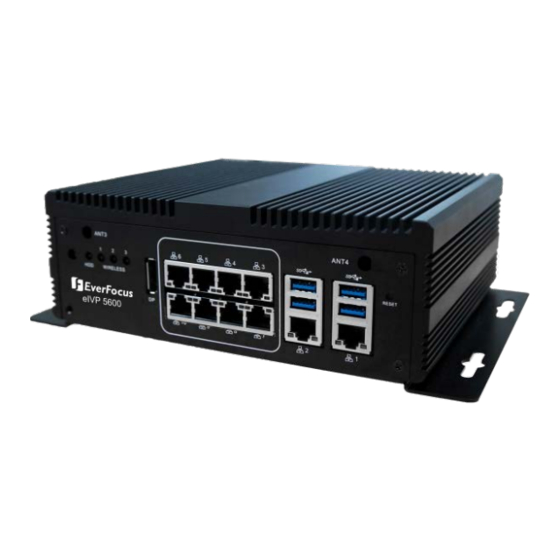
Page 10: Front Panel
AI Mobile NVR 1.4 Front Panel Name Description Power Button Press the button to turn on or turn off the system. Antenna Connects the antenna to the mobile NVR for 3G / 4G / WiFi functions. HDD: When storage is reading/writing data, the LED will flashes green. -
Page 11: Rear Panel
AI Mobile NVR 1.5 Rear Panel No. Name Description Antenna Connects the antenna to the mobile NVR for 3G / 4G / WiFi functions. CAN Bus CAN Bus 2.0B Connector. SIM Card Slot SIM Card slots. HDMI Port HDMI display output. -
Page 12: Connection And Installation
Chapter 2. Connection and Installation 2.1 Storage Installation The eIVP5600 supports mSATA and 2.5” SATA SSD for storage. 2.1.1 mSATA drive Installation Make sure the NVR is power-off. Unscrew the four screws on the bottom cover and then remove the bottom cover. - Page 13 AI Mobile NVR Lift up the case to remove the top cover. Turn the case to the other side and find the mSATA interface on the motherboard. Screw your mSATA drive to the mSATA Interface using the supplied mSATA Screw.
-
Page 14: Sata Ssd/Hdd Installation
AI Mobile NVR 2.1.2 2.5” SATA SSD/HDD Installation You can install one 2.5” SATA SSD/HDD inside the NVR. Make sure the NVR is power-off. Unscrew the four screws on the bottom cover and then remove the bottom cover from the housing. -
Page 15: Storage Compatibility List
SSD Power Cable Screw the bottom cover back to the housing. 2.1.3 Storage Compatibility List Please go to the product page (Download) on EverFocus’ Website www.everfocus.com.tw to see the latest Storage Compatibility List. It’s recommended to use the storage models listed on the... -
Page 16: Gps Antenna Installation
AI Mobile NVR 2.2 GPS Antenna Installation The eIVP5600 supports onboard GPS. To enable the GPS function, connect a GPS Antenna to the antenna port. 1. Make sure the NVR is power-off. 2. Unscrew the four screws on the bottom cover and then remove the bottom cover. -
Page 17: Ram Installation
AI Mobile NVR 2.3 RAM Installation The eIVP5600 supports 260-pin DDR4 2133 MHz SODIMM x 2. You can install the RAM on the DIMM port of the motherboard. 1. Make sure the NVR is power-off. 2. Unscrew the four screws on the bottom cover and then remove the bottom cover. -
Page 18: Dc Out Cable
AI Mobile NVR 2.4 DC Out Cable The eIVP5600 provides a total of 12V/2A DC output with four sets of power output wires (+/-) for the connected IP cameras. Connect the supplied DC Out Cable to the DC Out port on the rear panel of the NVR. -
Page 19: Jumpers And Connectors On The Motherboard
AI Mobile NVR Chapter 3. Jumpers and Connectors on the Motherboard Users can use the jumpers and connectors to configure different applications. Component Side... - Page 20 AI Mobile NVR Solder Side...
-
Page 21: List Of Jumpers
AI Mobile NVR 3.1 List of Jumpers You can refer to the jumpers listed as below to configure your application. Label Function CN10 Clear CMOS CN14 ATX/AT Selection CH15 COM1 Ring/ +5V/ +12V Selection CN16 CAN Bus UART/USB Selection... -
Page 22: Can Bus Program Firmware (Cn18)
AI Mobile NVR 3.1.5 CAN Bus Program Firmware (CN18) Function Protected (Default) Program... -
Page 23: List Of Connectors
AI Mobile NVR 3.2 List of Connectors You can refer to the connectors listed as below to configure your application. Label Function Power Button Software Reset Power on/off delay selection VGA1 CRT Port Power Button Front Panel Connector Board to Board Connector... -
Page 24: Front Plane Connector (Cn5)
AI Mobile NVR DIMM1 DIMM2 Slot DIMM2 DIMM1 Slot SLOT1 Mini Card Connector (only USB) half size SLOT2 Mini Card Connector (PCIe + USB) full size SLOT3 Mini Card Connector (only USB) full size MSATA1 Mini-SATA Connector SATA1 Primary Serial ATA Connector... -
Page 25: Com3 Rs-232 Serial Port Connector (Com2)
AI Mobile NVR 3.2.3 COM3 RS-232 Serial Port Connector (COM2) Signal Signal 3.2.4 COM1 & COM2 RS-232/422/485 Serial Port Connector (COM3) Signal Signal RXD (RS422 RX-) TXD (RS485 Data- DTR (RS422 RX+) /RS422 TX-) 3.2.5 Digital I/O Connector (CN20) -
Page 26: Power In & Remote Button (Cn19)
AI Mobile NVR 3.2.6 Power In & Remote Button (CN19) 1 2 3 4 5 6 Signal Signal GND_PRI PWR_IN REMOTE_SW PS_ON# 3.2.7 CAN Bus 2.0B Connector (CN22) Signal Signal CAN DATA + CAN DATA - 3.2.8 Power on/off delay select (SW3) -
Page 27: Ami Bios Setup
AI Mobile NVR Chapter 4. AMI BIOS Setup 4.1 System Test and Initialization The board uses certain routines to perform testing and initialization. If an error, fatal or non-fatal, is encountered, a few short beeps or an error message will be outputted. The board can usually continue the boot up sequence with non-fatal errors. -
Page 28: Ami Bios Setup
AI Mobile NVR 4.2 AMI BIOS Setup The AMI BIOS ROM has a pre-installed Setup program that allows users to modify basic system configurations, which is stored in the batter y-backed CMOS RAM and BIOS NVRAM so that the information is retained when the power is turned off. -
Page 29: Setup Submenu: Advanced
AI Mobile NVR 4.4 Setup Submenu: Advanced 4.4.1 Advanced: CPU Configuration Options summary: Active Processor Cores Number of cores to enable in each processor package. Hyper-Threading Disabled Enabled Enabled for Windows XP and Linux (OS optimized for Hyper-Threading Technology) and Disabled for... -
Page 30: Advanced: Pch-Fw Configuration
AI Mobile NVR 4.4.2 Advanced: PCH-FW Configuration Options summary: ME FW Image Re-Flash Disabled Enabled Enable/Disable Me FW Image Re-Flash function. 4.4.3 Advanced: SATA Drives Options summary: SATA Controller(s) Disabled Enabled Enable/Disable SATA Device. Hot Plug Disabled Enabled Designates this port as Hot Pluggable. -
Page 31: Advanced: Trusted Computing
AI Mobile NVR 4.4.4 Advanced: Trusted Computing Options summary: Security Device Support Disabled Enabled Enables or Disables BIOS support for security device. O.S. will not show Security Device. TCG EFI protocol and INT1A interface will not be available. TPM State... -
Page 32: Advanced: Hardware Monitor
AI Mobile NVR 4.4.5 Advanced: Hardware Monitor 4.4.6 Advanced: SIO Configuration... -
Page 33: Sio Configuration: Serial Port Configuration
AI Mobile NVR 4.4.6.1 SIO Configuration: Serial Port Configuration 4.4.6.2 SIO Configuration: Serial Port 1 Configuration... -
Page 34: Sio Configuration: Serial Port 2 Configuration
AI Mobile NVR Options summary: Use This Device Disabled Enabled Enable or Disable this Logical Device. Possible: Use Automatic Settings IO=2F8h; IRQ=3; IO=3F8h; IRQ=4; Allows user to change Device's Resource settings. New settings will be reflected on This Setup Page after System restarts. -
Page 35: Sio Configuration: Serial Port 3 Configuration
AI Mobile NVR 4.4.6.4 SIO Configuration: Serial Port 3 Configuration Options summary: Use This Device Disabled Enabled Enable or Disable this Logical Device. Possible: Use Automatic Settings IO=2F8h; IRQ=3; IO=3F8h; IRQ=4; Allows user to change Device's Resource settings. New settings will be reflected on this Setup Page after System restarts. -
Page 36: Sio Configuration: Serial Port 5 Configuration
AI Mobile NVR Options summary: Use This Device Disabled Enabled Enable or Disable this Logical Device. Possible: Use Automatic Settings IO=2F8h; IRQ=3; IO=3F8h; IRQ=4; Allows user to change Device's Resource settings. New settings will be reflected on this Setup Page after System restarts. -
Page 37: Sio Configuration: Serial Port 6 Configuration
AI Mobile NVR 4.4.6.7 SIO Configuration: Serial Port 6 Configuration Options summary: Use This Device Disabled Enabled Enable or Disable this Logical Device. Possible: Use Automatic Settings IO=2F8h; IRQ=3; IO=3F8h; IRQ=4; Allows user to change Device's Resource settings. New settings will be reflected on this Setup Page after System restarts. -
Page 38: Advanced: Power Management
AI Mobile NVR Options summary: DIO Port5~8 Output Set DIO as Output. Output Level High Set output level when DIO pin is output. 4.4.8 Advanced: Power Management Options summary: Power Mode ATX Type AT Type Select Power Supply Mode. -
Page 39: Setup Submenu: Chipset
AI Mobile NVR 4.5 Setup Submenu: Chipset 4.5.1 Chipset: System Agent (SA) Configuration... -
Page 40: System Agent (Sa) Configuration: Graphics Configuration
AI Mobile NVR 4.5.1.1 System Agent (SA) Configuration: Graphics Configuration Options summary: VT-d Enabled Disabled VT-d capability. Primary Display Auto IGFX Select which of IGFX/PEG/PCI Graphics device should be Primary Display Or select SG for Switchable Gfx. Primary IGFX Boot Display... -
Page 41: Setup Submenu: Security
AI Mobile NVR 4.6 Setup Submenu: Security Change User/Administrator Password You can set a User Password once an Administrator Password is set. The password will be required during boot up, or when the user enters the Setup utility. Please Note that a User Password does not provide access to many of the features in the Setup utility. -
Page 42: Setup Submenu: Boot
AI Mobile NVR 4.7 Setup Submenu: Boot Options summary: Quite Boot Disabled Enabled Enables or disables Quiet Boot option. Launch PXE ROM Disabled Enabled Controls the execution of UEFI and Legacy PXE OpROM 4.8 Setup submenu: Save & Exit... -
Page 43: Specification
AI Mobile NVR Chapter 5. Specification Model No. eIVP5600 Processor Intel® 7th Gen. Core™ i5/i7 Processor System Main Memory Up to 32GB, DDR4 260-pin SODIMM (optional) Format H.264 / H.265 Video Video Input Up to 8 IP cameras Video Output... - Page 44 AI Mobile NVR DC-In power x 1 Remote power x 1 8-bit DIO x 1 4ch digital input (wet/dry contact with Isolation Protection 3,000 VDC) 4ch digital output (compatible 5 V/TTL, 31mA max. per channel) Rear I/O Panel DC 12V/1A output x 1...
- Page 45 FAX: +81 3 5625 8189 www.everfocus.com www.everfocus.co.jp sales@everfocus.com info@everfocus.co.jp Ihr EverFocus Produkt wurde entwickelt Your EverFocus product is designed and und hergestellt mit qualitativ manufactured with high quality materials hochwertigen Materialien und and components which can be recycled Komponenten, die recycelt und wieder and reused.
Need help?
Do you have a question about the eIVP5600 and is the answer not in the manual?
Questions and answers