Table of Contents
Advertisement
Quick Links
Advertisement
Table of Contents

Related Manuals for Pfeiffer Vacuum HPA 220


Summary of Contents for Pfeiffer Vacuum HPA 220
- Page 1 High Pressure Analyser HPA 220 Operating Instructions...
-
Page 2: Table Of Contents
Double gate valve, electropneumatically operated......33 Gas inlet valve UDV 040 ..............34 Commissioning ................35 Commissioning QME................ 35 Commissioning HPA 220 ..............37 Operation ..................43 Indicator and control elements BRU 220.......... 43 HPA 220 ................... 43 Valve control ..................44 Measurement ................... - Page 3 11.2 Recommissioning ................50 Disposal ..................51 Malfunctions ................... 51 13.1 Troubleshooting ................51 Appendix ..................53 14.1 Block diagrams................. 53 14.2 Literature ..................54...
-
Page 4: About This Manual
*also available at www.pfeiffer-vacuum.de 1.2 Conventions Safety instructions Safety instructions in Pfeiffer Vacuum operating manuals are the result of the risk evaluations and danger analyses that were performed and that are based on international certification standards according to UL, CSA, ANSI Z-535, Semi-S1, ISO 3864 and DIN 4844. - Page 5 Base rack unit High pressure analyser Input output Valve control unit Diaphragm vacuum pump Symbols used The symbol [X] is used for references to further documents listed under the Literature section. Trademarks PrismaPlus™ Pfeiffer Vacuum GmbH QUADERA™ INFICON AG...
-
Page 6: Safety
NOTE Installation and operation of accessories Pfeiffer Vacuum Units can be equipped with a series of adapted accessories. The installation, operation and maintenance of connected devices are described in detail in the operating manuals of the individual components. -
Page 7: Proper Use
Wear hearing protection 2.3 Proper use The High pressure analyser HPA 220 is used in the analysis of non-flammable gases and gas mixtures with process pressures of less than 10 mbar. The actual pressure range depends on the screens attached. -
Page 8: Improper Use
Directive for electrical equipment 2006/95/EC 3 Transport and storage 3.1 Transport Reuse the HPA 220 transport container. The unit should be transported or shipped in the original packaging. Remove protective caps from the high vacuum side and backing side just before connecting. -
Page 9: Product Description
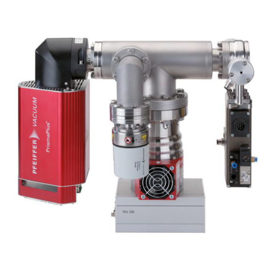
BRU 220 MVP 020 with PKR 251 QMA 200 QME 220 HiPace80 VCU 220 DCU002 TPG26x Selection of inlet systems and options for HPA 220 Operating Feature HPA 220 manual HPI 040 H 250986 NA HPI 040 P 250986 NA... -
Page 10: Function
The system can be operated manually via the BRU 220 and the Quadera software as well as via corresponding inputs from a higher-level system control. 4.3 Field of application The HPA 220 must be installed and operated the following ambient conditions only: DANGER Explosion hazard The HPA 220 is not intended for use in potentially explosive areas. -
Page 11: System Overview
Product description 4.4 System overview Quadrupole electronics QME 220 with 90° connection With the mass range according to option: PT M51 xxx 1-100 amu PT M52 xxx 1-200 amu PT M53 xxx 1-300 amu Analyser QMA 200 With the ion source according to option: PT M5x 1xx open ion source, Y filament with pressure... - Page 12 Product description Mains cable Connection cable set Standard cable (with all options included) Cable Art. no. (3m) Art. no. (10m) Cable markings Interface cable M12 PM 061 283-T PM 061 285-T Connection cable BRU/TC PM 061 512-T PM 061 514-T Turbo pump Connection cable BRU/MVP PM 061 441-T...
- Page 13 Product description Cable set optional components: Option Cable Art. no. (3m) Art. no. (10m) Cable markings PT M5x x2x Connection cable VCU/PP PT 165 070-T Digital I/O PT M5x x4x PT M5x x2x Connection cable VCU/HPI PT 165 073-T Valves PT M5x x4x Connection cable VCU/DZS PT 165 072-T...
- Page 14 Product description Diaphragm pump MVP 020 [5] Inlet valve variants HPI 040 H, manually operated - for option PT5x x1x HPI 040 P, electropneumatically operated - for option PT M5x x2x Double gate valve, manually operated - for option PT M5x x3x...
- Page 15 Product description Double gate valve, electropneumatically operated - for option PT M5x x4x UDV 040, manually operated - for option PT M5x x5x VCU 220 - only for option PT M5x x2x and PT M5x x4x Additional components Display and control unit DCU 002 integrated into BRU (PM 061 348-T) [7]...
- Page 16 A total pressure vacuum gauge from the ActiveLine family with connection cable must be provided separately, depending on the working pressure range. [13] Heating option Heating unit composed of controller and heating jacket (Pfeiffer Vacuum GmbH; PT 165 000-T [230V] or PT165 001-T [115V])
-
Page 17: Technical Data
Technical data 5 Technical data 5.1 HPA 220 HPA 220 Mass range 1...100 1...200 1...300 Faraday 5x10 5x10 2x10 Detection limit, min mbar C-SEM 1x10 1x10 4x10 Faraday 5x10 3x10 1.5x10 Sensitivity to Ar A/mbar Interference from neighbouring mass 40/41 Operating temperature, °C... -
Page 18: Hpa 220
Technical data HPA 220 Weight (analyser unit with 11.8 TMP, PKR and PrismaPlus; without valve interface) Valve interface HPI 040 Double gate valve UDV 040 Actuation electropneum. manual electropneum. manual manual Compressed air 5...7 5...7 Compressed air connection 1/8" female 1/8"... -
Page 19: Qme 220
Technical data 5.2 QME 220 QME 220 Measurement system – Measurement channels – Measuring modes Analogue scan, bargraph scan, MID, MCD – Measuring cycles Mono/multichannel 1... 9999 cycles or repeat – Measuring speed – Analogue scan+bargraph peak 20 ms/u...60ms/u – Scan bargraph stair 2ms/u...60s/60u –... -
Page 20: Input/Output Module Io 220
Technical data 5.3 Input/output module IO 220 IO 220 Analogue inputs – Connection (“analogue I/O”) X7, 15 pole D-Sub socket – Number of channels – Input configuration differential – Input voltage range nominal ± 10V, max. ± 14 V to GND –... -
Page 21: Base Rack Unit (Bru 220)
Technical data The actual number of DO/DI depends on the gas inlet system used. All 16 DO are available for manual operation, 13 for electropneumatic operation (the DO 14-16 are used for controlling). All DI are available for manual operation. Only DI4 is available for option PT M5x x2x. -
Page 22: Dimensions
Technical data 5.7 Dimensions HHPA 220 * only for options with electropneumatic valve control 5.8 Connection plug arrangement IO 220 digital I/O VACUUM VACUUM... - Page 23 Technical data NOTE This output is not available for option PT M5x x2x and option PT M5x x4x Please refer to section “VCU 220”, page 25 Output “X2” can be used without restrictions for options PT M5x x0x, PT M5x x1x, PT M5x x3x and PT M5x x5x.
- Page 24 Technical data VCU 220 The “Digital I/O” port has, with few exceptions, all inputs and outputs of port “X2” of the IO 220 module. The I/O channels of the IO 220 are thus available to a limited extent. CAUTION Destruction of the gas inlet system When using the digital outputs DO1-DO3 in a way that deviates from the specifications for the PrismaPlus™...
- Page 25 Ground (0V) for digital inputs not assigned unavailable The control input “External” is available for integrating the HPA 220 into existing control concepts (e.g. PLC). Using an external relay or open collector circuits, the pins of the input can be bridged in order to activate or deactivate the corresponding valves.
- Page 26 Technical data Description 15 pole D-Sub 24V DC 24V DC 24V DC NOTE If you do not use any external control, the supplied “External” plug must be plugged into the corresponding socket of the Valve Control Unit. This Sub-D plug has internal bridges to enable the valve control. Otherwise the valves are not opened.
- Page 27 BRU 220 Rear view BRU 220 The base rack unit offers the opportunity to integrate the HPA 220 into an existing control ( e.g. a PLC). It is connected to the D-Sub plug “User”. The heating, equipment and valve interlock can be connected. The entire system, the valve control and the heating jacket can be interlocked via the bridging of pins at this input (see chapter “Schematic...
- Page 28 Heating interlock NOTE All interlocks must be activated in order to put the HPA 220 into operation. Use the HPA 220 without external devices/controllers; plug the supplied “User” plug into the appropriate socket. This Sub-D plug has internal bridges for all three interlocks.
-
Page 29: Gas Inlet Systems
Gas inlet systems 6 Gas inlet systems The HPA 220 is delivered with different gas inlet systems, depending on option. They can be operated either manually or electropneumatically, depending on the version. PT M5x x1x HPI040 H, manual PT M5x x2x... - Page 30 Gas inlet systems Valve control Valves V1, V2 and V3 are controlled using the Valve Control Unit. It is actuated by the PrismaPlus™. The Quadera software opens and closes the valves by switching the corresponding digital outputs. Output assignment: (see also section “IO 220 digital I/O”, page 23 or “VCU 220”, page 25) DO 14 DO 15 DO 16...
-
Page 31: Double Gate Valve Operated Manually
Gas inlet systems After startup, a query window for selecting either manual or external control appears. Fig.: Selection window for manual/external control If you select “External”, the relays of the VCU change all valves over to external control via the “External” connector assembly. (see “VCU 220”, page 25) If you select “Manual (using GUI)”, the valves can be opened or closed individually in the next window via the corresponding control buttons. -
Page 32: Double Gate Valve, Electropneumatically Operated
Gas inlet systems Control, operation WARNING Risk of filament destruction and analyser contamination If the valve is opened when there is insufficient vacuum, gas flows into the vacuum chamber, which can result in oxidation and destruction of the hot cathode. ... -
Page 33: Gas Inlet Valve Udv 040
Gas inlet systems If a DO is set to “active”, the corresponding valve opens. Fig.: Manual valve control 6.5 Gas inlet valve UDV 040 Function The UDV is a manually operated valve. It covers a wide pressure range of 10 …... -
Page 34: Commissioning
Commissioning 7 Commissioning DANGER Damaged product The commissioning of a damaged product can be extremely dangerous. In case of visible damage, protect the product against inadvertent operation. NOTE Caution: Vacuum components Dirt and damage impair the function of the vacuum components. ... - Page 35 Commissioning WARNING If the mounting flange is not earthed, the flange of the QME (ground terminal screw M4) must be connected to the protective earth by means of a separate ground wire. Use yellow-green or bare copper wire for this ground wire: •...
-
Page 36: Commissioning Hpa 220
Turn on the PC and install the supplied Quadera software. 7.2 Commissioning HPA 220 Mechanical The HPA 220 is designed to be mounted directly onto a CF40 flange (Cajon VCR 1/4" for UDV 040). Please make sure that no other mechanical forces other than its own weight installation are acting on the unit. - Page 37 Commissioning NOTE We recommend propping up the entire system under HiPace 80 or under the VCU 220 (depending on option). Ensure the unit has a secure footing. Compressed air is required for all options with electropneumatically operated valves. There is a 1/8" threaded connector for the connection to the compressed air system on every valve.
- Page 38 Commissioning • Connect the output “PrismaPlus” on the BRU to the 24V input on the PrismaPlus™. Use the cable marked “PrismaPlus”. • Connect the output “Diaphragm Pump” on the BRU to the mains input on the MVP. Use the cable marked “MVP”. •...
- Page 39 Commissioning • Connect the output “DO1” of the turbopump controller on top of the D-Sub plug to the input “Switch Point” on the BRU. Use the cable marked “Switch Point”. • Connect the “Digital I/O” terminal on the PrismaPlus™ with the input “Prisma Plus” on the VCU.
- Page 40 • Connect the sealing gas valve on the side of the turbopump with the plug “B1”. It is located on the turbopump controller. Use the cable marked “venting valve”. • Use the HPA 220 without external devices/controllers; plug the supplied “User” plug into the appropriate socket on the base rack unit.
- Page 41 Commissioning • Use the valve control unit without external devices/controllers; plug the supplied “External” plug into the appropriate socket on the valve control unit. • For options with heating, connect these to the output “Heater” on the BRU. Also connect the current supply of the heating jacket to the control unit.
-
Page 42: Operation
8.2 HPA 220 Insert the mains plug The HPA 220 is turned on via the master switch on the front side of the base rack unit. The diaphragm pump starts automatically and evacuates the vacuum chamber. The turbopump also starts automatically. -
Page 43: Valve Control
Operation Once 80% of the set rotation speed is reached, the relay K1 is activated (compare Schematic representation of the BRU, page 53). As of this point, the PrismaPlus™ and the heating can be switched on. The corresponding switches are located on the front side of the base rack unit. -
Page 44: Switching Off
Operation 8.7 Switching off If not yet carried out, switch the PrismaPlus filament off via the Quadera software. Disconnect it from the unit and close Quadera [1] Switch off the heating and the PrismaPlus™ using the appropriate switches on the front of the base rack unit. -
Page 45: Maintenance / Servicing
The following steps are necessary for quick and frictionless handling: Download the service request and contamination declaration. Fill out the service request and send it by fax or e-mail to your Pfeiffer Vacuum Service address. Enclose confirmation of the service request by Pfeiffer Vacuum and include it in your shipment. -
Page 46: Qme
Maintenance / servicing 9.1 QME The dust filter on the air inlet must be cleaned as soon as a clearly visible coating has accumulated. Use a vacuum cleaner to remove the dust from the filter. The QME can stay connected to the QMA for this work. A slightly damp cloth normally suffices for cleaning the exterior. -
Page 47: Replacing Hipace 80 Operating Fluid Reservoir
Maintenance / servicing 9.2 Replacing HiPace 80 operating fluid reservoir WARNING Poisoning hazard through contact with harmful substances The operating fluid reservoir and parts of the pump may contain toxic substances from the pumped media. Dispose of operating fluid reservoir in accordance with the applicable regulations. Safety data sheets on request at www.pfeiffer-vacuum.de ... -
Page 48: Accessories And Spare Parts
Accessories and spare parts 10 Accessories and spare parts 10.1 Accessories and spare parts PrismaPlus™ [2] 10.2 Accessories and spare parts for HiPace 80 10.3 Connection cable Item Designation Length Article no. Interface cable M12 PM 061-283-T Connection cable BRU/TC PM 061 512-T Connection cable BRU/MVP PM 061 441-T... -
Page 49: Decommissioning
Clean the complete system externally with a lint-free cloth and a little industrial alcohol. If necessary, have the Pfeiffer Vacuum Service clean the turbopump completely. Remove all blank flanges. Install and commission in accordance with manual. -
Page 50: Disposal
BRU 220 device fuse has Check and replace fuse responded Incorrect operating Apply correct operating voltage voltage Observe the ratings on the type plate. Power supply pack TPS 3 Replace power supply pack, is defective contact Pfeiffer Vacuum Service. - Page 51 See problem description “Pump system reaching final rotational neither reaching final speed nor pressure” speed Please refer to the relevant operating manuals for information about malfunctions on individual components. For any further question you may have, please contact Pfeiffer Vacuum Service.
-
Page 52: Appendix
Appendix 14 Appendix 14.1 Block diagrams Schematic representation of the BRU Gate valve open/close > Switch Main on/off V1 open/close > TPG 26x 100-240 VAC V2 open/close > (Option) < 100-240 VAC, switched Switch on/off Heater PrismaPlus (Option) 24 VDC 24V Prisma+ switched TPS 311 Switch heater... -
Page 53: Literature
Appendix 14.2 Literature [1] www.pfeiffer-vacuum.com Quadera Help (includes CD-R) Pfeiffer Vacuum GmbH, D-35614 Asslar, Germany [2] www.pfeiffer-vacuum.com Operating manual Compact mass spectrometer Prisma Plus QMG220 BG5214BEN Pfeiffer Vacuum GmbH, D-35614 Asslar, Germany [3] www.pfeiffer-vacuum.com Communication manual Prisma™ QMS 200... - Page 54 Compact full range gauge PKR 251 BG5155BEN http://www.pfeiffer-vacuum.de/produkte/messgeraete/activeline/container.action [10] www.pfeiffer-vacuum.com Operating manual All-metal control valve UDV 040 BP5003BEN Pfeiffer Vacuum GmbH, D-35614 Asslar, Germany [11] www.vatvalve.com Operating manual Mini UHV vane RGA valve 250986DA VAT Vakuumventile AG, CH-9469 Haag, Switzerland ...
- Page 55 Declaration on contamination of vacuum units and components Download form at www.pfeiffer-vacuum.com...
- Page 56 In addition, the product satisfies, within certain voltage limits, all relevant provisions of the EU Directive for electrical equipment 2006/95/EC. The agent responsible for compiling the technical documentation is Dr. Falk Braunschweig, Pfeiffer Vacuum GmbH, Berliner Straße 43, 35614 Aßlar, Germany. High pressure analyser HPA 220...
- Page 57 Leading. Dependable. Pfeiffer Vacuum stands for innovative and custom Customer Friendly vacuum solutions worldwide. For German engineering art, competent advice and reliable services. Ever since the invention of the turbopump, we´ve been setting standards in our industry. And this claim to leadership will continue to drive us in the future.
Need help?
Do you have a question about the HPA 220 and is the answer not in the manual?
Questions and answers