Table of Contents
Advertisement
WYLER AG
Tel. 0041 (0) 52 233 66 66
Im Hölderli
Fax. 0041 (0) 52 233 20 53
CH-8405 WINTERTHUR
Switzerland
Homepage: http://www.wylerag.com
E-Mail:
wyler@wylerag.com
Manual
Blue
BlueLEVEL BASIC
-
BlueMETER
BASIC
WyBUS-Technology
Two BlueLEVEL BASIC with BlueMETER BASIC
with wireless data transmission
Advertisement
Table of Contents

Related Manuals for WYLER BlueSYSTEM BASIC


Summary of Contents for WYLER BlueSYSTEM BASIC
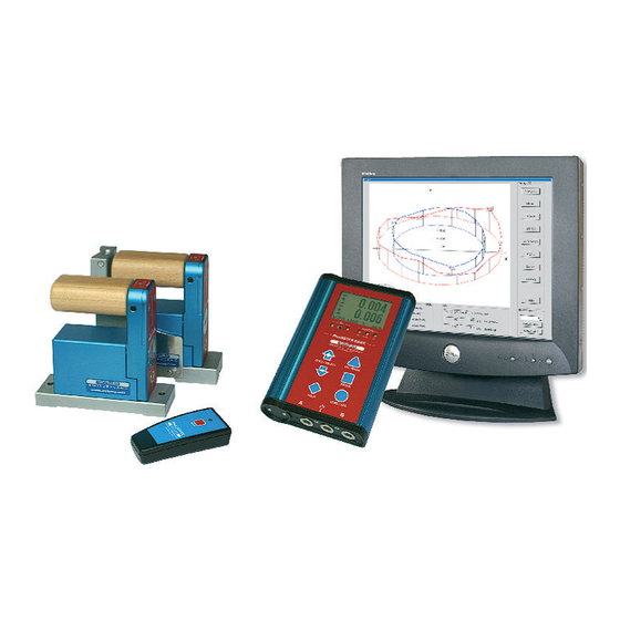
- Page 1 WYLER AG Tel. 0041 (0) 52 233 66 66 Im Hölderli Fax. 0041 (0) 52 233 20 53 CH-8405 WINTERTHUR Switzerland Homepage: http://www.wylerag.com E-Mail: wyler@wylerag.com Manual Blue BlueLEVEL BASIC BlueMETER BASIC WyBUS-Technology Two BlueLEVEL BASIC with BlueMETER BASIC with wireless data transmission...
-
Page 3: Table Of Contents
EIGHT RELATED TO THE STEP LENGTH ZERO) ERO SETTING BY REVERSAL MEASUREMENT BSOLUTE PPLICATIONS EASURING ABSOLUTE ELATIVE EASUREMENT IFFERENTIAL RESPECTIVELY REFERENCE MEASUREMENT USING AN ENGINEER SET NGULAR MEASUREMENTS INES AND FLATNESS MEASUREMENT MANUAL PROCEDURE WYLER LEVELSOFT PRO SOFTWARE page 3 of 84... - Page 4 OFTWARE FOR THE DEFINITION OF MACHINE TOOL GEOMETRY MT-SOFT MACHINE TOOL INSPECTION SOFTWARE XAMPLE USING THE YPER ERMINAL OF INDOWS OR INDOWS ERMINAL PROGRAM US COMPATIBLE INSTRUMENTS ONNECTION THROUGH A SHORT CABLE ONNECTION THROUGH A LONG PECIAL UNCTIONS ESET TO ACTORY PRE SETTINGS IRMWARE...
- Page 5 Modifications: Date Modified by Description of modifications 5.2.2008 New with wireless data transmission 01.05.2009 HEH / TRA New with WyBus technology page 5 of 84...
-
Page 6: Basics / Introduction
ASICS NTRODUCTION The new BlueSYSTEM BASIC series has been developed as a basic model to the well known and well proven measuring instruments of the BlueSYSTEM family with wireless data transmission. Compared to the existing systems with wireless data transmission the BlueSYSTEM BASIC series has an excellent price/performance ratio and is easier to operate. -
Page 7: Preparation Ands
REPARATION AND TART UP OF THE MEASURING INSTRUMENTS EFORE STARTING INSERTING RESPECTIVELY LEVEL BASIC REPLACEMENT OF BATTERIES IN METER BASIC 2.1.1 E METER BASIC XCHANGE OF BATTERIES IN THE The batteries are not installed in the new instruments they are delivered separately. It is recommended to remove the batteries when transporting the instruments. -
Page 8: Initial Start
• The operation "Combine a group of Instruments" described in chapter 2.4 has already been done at WYLER's when the instruments are delivered. • If a configuration is shut off, e.g. after completion of a measurement, the group-setup remains saved. -
Page 9: Connecting The Instruments
LEVEL BASIC METER BASIC) ONNECTING THE INSTRUMENTS • LEVEL BASIC ABLE CONNECTION FOR INSTRUMENT "A" ONNECTOR • ABLE CONNECTION FOR EXTERNAL POWER SUPPLY • ONNECTION TO OR LAPTOP • ABLE CONNECTION FOR EXTERNAL POWER SUPPLY • LEVEL BASIC ABLE CONNECTION FOR INSTRUMENT "B"... -
Page 10: Combine A
"JOIN" OMBINE A ROUP OF NSTRUMENTS USING THE FUNCTION The function "JOIN" enables the grouping of instruments through wireless data transmission. The grouping prevents the accidental reading of measuring values from instruments of another measuring group. The function "JOIN" can be performed using the cable connection or with wireless data transmission. -
Page 11: Procedure "Leave
2.4.2 "LEAVE" ROCEDURE Using the function "LEAVE" unleashes an existing measuring group. 1. Press the <ON/MODE> button on the BlueMETER BASIC repeatedly until the menu [LEAVE] appears on the display. Confirm with <ENTER>. 2. During the log-off the blue LED under "LINK" is lit continuously, the green LED "READY"... -
Page 12: Description And Function Of The
LEVEL BASIC ESCRIPTION AND FUNCTION OF THE WITH AND WITHOUT RADIO MODULE Starting the BlueLEVEL BASIC The BlueLEVEL BASIC is started using the <ON/MODE> and <ON> keys located opposite on the handle. The two keys must be pressed simultaneously until all the LEDs on the top of the handle are lit. In case the BlueLEVEL BASIC is connected to a BlueLEVEL BASIC with external power supply, the BlueLEVEL BASIC is started automatically when the BlueMETER BASIC is switched on. -
Page 13: View Of Functional Keys
LEVEL BASIC IEW OF FUNCTIONAL KEYS 3.2.1 EAR VIEW LED functions indicator (see separate picture) key "ON/OFF" key "ON" Batteries Connector RS422 / RS485 BlueLEVEL BASIC BlueLEVEL BASIC with wireless data with cable transmission 3.2.2 LEVEL BASIC OP VIEW OF THE WITH RADIO IR-receiver (infrared) LED-blue, “LINK“... - Page 14 3.2.3 LEVEL BASIC OP VIEW OF THE WITHOUT RADIO IR-receiver (infrared) LED-blue, “AUX“ not used LED-green, "OK", lit continuously: Power supply "O.K." LED-red blinking: Power supply "insufficient" no further measurements possible.- on the BlueMETER BASIC display a remark appears instead of the mesuring value, saying that the measuring instrument is not sufficiently powered.
-
Page 15: Description Of The 4.1 Starting The Blue
- Address of instruments/sensors, port definition (Port) - Filter-settings - Relative base length etc. It is possible to send measured data via a RS 232 port to a printer, a PC/Laptop or the WYLER software LEVELSOFT PRO, MT-SOFT and LabEXCEL •... -
Page 16: Typical Configurations With
METER BASIC LEVEL BASIC YPICAL CONFIGURATIONS WITH Configurations using BlueLEVEL BASIC instruments and BlueMETER BASIC Data transmission via cables Configurations with wireless data transmission Configurations with data transmission via cables and with connection to a PC/Laptop Configurations with wireless data transmission and with connection to a PC/Laptop Remarks: Systems equipped with wireless data transmission can alternatively be used with cable connection. - Page 17 Overview of the B METER BASIC Large LCD display with actual measured value, instrument’s address and measuring unit LED showing activities Status power supply and transmission and infrared contact. Panel with functional keys Aluminium housing anodized Battery compartment Connectors for instruments/sensors/power supply and output to PC/Laptop...
-
Page 18: Functional Menu With
METER BASIC UNCTIONAL MENU WITH USING THE FUNCTION KEY according to G. Lasczyk) using the key <ON/MODE> on the BlueMETER BASIC only Switching the - Switching on the display instrument BlueMETER BASIC. Press the <ON/MODE> key instrument on until all 5 LED‘s are illuminated then release the key and "SYSTEM CHECK" is shown on the display. - Page 19 Possible error messages in the status line of the display: cont. SENSOR (BlueMETER BASIC only) • "no sensor": no sensors found yet. NO sensors are connected via cables and no instruments with wireless data transmission are registered. In case the sensors should have been connected through cables, a REFRESH must be performed after these have been connected.
- Page 20 cont. - Possible error messages in the display: SENSOR (BlueMETER BASIC only) • When starting the system a cross between to arrows appears (picture above) • If a cross between two arrows appears this is a hint that the sensor is listed in the configuration of instruments but cannot be detected due to one of the following reasons: The measuring instrument is not switched on...
- Page 21 REL.ZERO With one instrument (Display on the BlueMETER BASIC only) (BlueMETER BASIC only) Relative measured value (In the relative mode a "ZERO-OFFSET" determined e.g. by reversal measurement is superimposed by the value "REL ZERO OFFSET") Use the key <ON/MODE> select the menu [REL.ZERO] and confirm with <ENTER>. First the following picture is shown in the display of the BlueMETER BASIC.
- Page 22 Cont. Option / Manual setup REL.ZERO Use the key <ON/MODE> select [REL.ZERO] and confirm with <ENTER>. First the following picture is shown in the display of the BlueMETER BASIC (BlueMETER BASIC only) Use <ON/MODE> for cancelling the procedure The following picture is seen. It shows an earlier value for a ZERO OFFSET. ±...
- Page 23 REL.ZERO (BlueMETER BASIC only) Use <ENTER> or the IR-zapper for confirming the choice. The actual values are collected and constantly displayed. When the values have stabilized the relative ZERO can be confirmed with <ENTER> or with the IR-zapper. On the display of the BlueMETER BASIC the value "0.000" is seen. This is now the relative value considering the offset.
- Page 24 UNIT Setting the measuring unit. The desired measuring unit can be selected by repeatedly pressing the key <ON/MODE> until (BlueMETER the selection pointer is below the function UNIT. Confirm with the <ENTER> key. BASIC only) The following measuring units can be chosen at the BlueMETER BASIC: XXX.XXX New degree, 3 decimals XX.XXXX...
- Page 25 ABS.ZERO Setting of absolute ZERO with a reversal measurement. Using the reversal measurement is a simple way to determine the exact ZERO OFFSET of the (BlueMETER instrument as well as the exact inclination of the surface where the instrument is placed. BASIC only) •...
- Page 26 • When the curve is getting a straight line confirm the second value with the zapper or Cont. ABS.ZERO with <ENTER> (BlueMETER • After the second reading the following display is seen: BASIC only) With this the reversal measurement is finished and the instrument shows the true absolute value.
-
Page 27: Dditional Functions Of
RADIO Switching the wireless transmission ON respectively OFF (using cables / save on batteries!) Select the Menu [RADIO] using the key <ON/OFF> and confirm with <ENTER>. For definitively switching the wireless transmission ON or OFF confirm again with <ENTER>. As a sign that the radio transmission is switched off, the red LED on the handle will be ON. The switching on of the wireless transmission is done in the same way. -
Page 28: Teach-In Of The Ir
TEACH-IN of the IR-trigger (Zapper) to the BlueMETER BASIC and to the BlueLEVEL BASIC) In order to eliminate interference of the zapper signals when several measuring groups are active in the triggering range the IR trigger can be assigned to a specific measuring group by applying the function TEACH-IN Procedure TEACH-IN: •... -
Page 29: Operating The Blue
METER BASIC PERATING THE 4.6.1 ESCRIPTION OF THE VARIOUS KEYS <ON/MODE> - Key Function - 1 – Starting the BlueMETER BASIC. Press the <ON/MODE> key until all the 5 LED‘s are illuminated and on the display it is shown "SYSTEM TEST". After starting the actual measured value as well as the last used unit is displayed. - Page 30 <ENTER> – Key The key <ENTER> is used for saving data or for confirming taken actions. Function – 1 – Function - 2 - In connection with the software LEVELSOFT PRO and MT-SOFT the key is used for collecting the actual measured value. Function –...
- Page 31 <ZERO/SELECT ±> - Keys Function - 1 - The keys <ZERO/SELECT ±> are used for selecting different settings, such as: Measuring unit Ports ( "A" / "B" / "A - B" / "A B") Relative base settings Set "Zero-Offset" Set "REL Zero-Offset" etc. Function - 2 - Adjustment of display contrast <HOLD>...
-
Page 32: Description Of Various Display Forms On The
4.6.2 METER BASIC ESCRIPTION OF VARIOUS DISPLAY FORMS ON THE Main display Display of the actual measured value Display in [mm/m] Display in [mm/m] The display of the BlueMETER BASIC The display of the BlueMETER BASIC shows the difference value between shows the measured values of the instrument "A"... - Page 33 Status of battery power "BATT" BlueLEVEL BASIC Battery indication o the BlueLEVEL BASIC without radio module without radio • LED-blue, "AUX": not used Verwendung • LED-green, "OK", lit continuously: Power supply "O.K." • LED-green, "OK" lit continuously and the battery symbol (see illustration next page) in the display oft he BlueMETER BASIC is blinking: Power supply "sufficient".
- Page 34 Battery indicater Usually the actual battery power is displayed. E.g. 4 (4.2 Volt) "BATT" Regarding the status indication of the internal power the following options BlueMETER BASIC are possible: Usually the actual battery power is displayed, e.g. 36 (3.6 Volt) Regarding the status indication of the internal power the following options are possible: Note:...
- Page 35 Measuring unit Display of the actual unit set Key lock The symbol indicates that the instrument is performing a critical action and that all keys and entries are blocked. Display of active port address Sensor-Address Function – 1 - of the instrument showing the measured value - connected instrument/sensor used for calibration Function - 2 Display of the measuring mode, e.g.
-
Page 36: Appendix A Basics And General Remarks About
SYSTEM BASIC NTRODUCTION TO THE The new BlueSYSTEM BASIC series has been developed as a basic model to the well known and well proven measuring instruments of the BlueSYSTEM family with wireless data transmission. Compared to the existing systems with wireless data transmission the BlueSYSTEM BASIC series has an excellent price/performance ratio and is easier to operate. - Page 37 Display unit with various functions also serving as available interface between PC/Laptop. The BlueMETER Basic is available only without radio module. Common features of all the BlueSYSTEM BASIC family instruments: • One international standard in Bluetooth™ wireless technology, if equipped with the radio modules •...
- Page 38 BlueLEVEL BASIC with flat horizontal base BlueLEVEL BASIC with prismatic angular base BlueMETER BASIC page 38 of 84...
-
Page 39: Easuring Procedure
EASURING PROCEDURE ENERAL HANDLING YPICAL CONFIGURATIONS WITHOUT RADIO TRANSMISSION Used as stand alone instruments not possible as no display on the instruments. A BlueMETER BASIC is needed. Available sensitivities: • 1µm/m (0.2 ArcSec) • 5µm/m (1 ArcSec) • 10µm/m (5 ArcSec) Data transmission via cables Two BlueLEVEL BASIC and one BlueMETER BASIC... -
Page 40: A4 Basic Setup Of The Inclination Measuring Instruemnts
ASIC SETUP OF THE INCLINATION MEASURING INSTRUEMNTS MINUS RULE The instrument should always be placed in a way that the cable output is on the right hand side. Inclined to the right: positive Declined to the right: negative (Practical remark: positive values indicate that some material may be removed on the measured piece) Before starting the measurement enough acclimatisation time must be allowed for the instruments. -
Page 41: A5 Absolute Measurement
Practical example Position defined of the vertical spindle in relation to the machine table of a machine tool. Measurement with WYLER- software MT-SOFT Relative measurement (Relative ZERO) A number of measurements do not require the absolute ZERO as described above. - Page 42 Example: Measuring the flatness of a machine bed. The reference instrument is placed on a stable part of the machine where the measurement is not interfered. With the measuring instrument the measurement is taking place without removing the reference instrument. Practical example Flatness measurement with WYLER-software LEVELSOFT PRO page 42 of 84...
-
Page 43: Eneral Remarks About
" " " " ENERAL REMARKS ABOUT ANGLES INCLINATION Every angle may be defined in different ways. The most popular way is a definition in Degrees / Minutes / Seconds. This is shown in the graph. Such a definition is especially useful for larger angles. -
Page 44: A7 Height Related To The Step Length
EIGHT RELATED TO THE STEP LENGTH × Height Hx in [µm] related to Height µm Steplength Height Hx [µm] = step length Length × Height mikroINCH Steplength Inch Height Hx [micro Inch] = Height Hx in [micro Inch] Length Inch related to step length →... -
Page 45: A8 Zero Setting By Reversal Measurement
ZERO) ERO SETTING BY REVERSAL MEASUREMENT BSOLUTE Using the reversal measurement is a simple way to determine the exact zero point deviation of the instrument (which can thus be compensated) as well as the exact inclination of the surface the instrument is placed Reversal measurement for determining I. - Page 46 After the first reading the following display is seen: This display means the first reading was successful. The instrument must be turned 180 degrees without lifting and slid exactly onto the previously marked position Use the zapper or confirm with <ENTER>. On the display the progress of the collected values are again visible in graphic form.
-
Page 47: B Applications
(absolute ZERO). If e.g. the straightness of a line is measured most of the time the relative straightness is only required. The same applies when lines, parallels, flatness is measured with the WYLER LEVEL SOFT PRO. These are relative measurements. - Page 48 Examples for differential / reference measurement: R = Reference instrument, connected to port "B" M = Measuring instrument, connected to port "A" Rectangularity resp. parallelism of machine spindle in relation to work table (Fig. 7). For precise square measurements an angular model fitted with magnets in the vertical face should be used. (Elimination of deformation due to manual pressure).
- Page 49 Inspection of perpendicularity and parallelism on large structures (Fig. 9). Suitable instrument for outdoor applications. To conduct high precision measurements of parallelism (Fig 10) (e.g. guide way rails two or more) The reference instrument (R) will compensate for all changes in the objects orientation while measurements are made.
-
Page 50: B4 Angular Measurements
The determination of the instrument's angular error is done as follows: Index of correction = {(C + D)/2} - {(A + B)/2} In the WYLER LEVELSOFT PRO a new set-up allows the easy measurement of squareness of rectangular objects. Principal procedure of a 90° measurement with WYLER LEVEL SOFT PRO The angular error of the instrument must be determined (optional) The measurement follows the required set-up (Step length, number of measurements etc.) - Page 51 INES AND FLATNESS MEASUREMENT MANUAL PROCEDURE A principal procedure of a measurement of a line with WYLER instruments is described below: Example: • Sensitivity of the instrument 1 µm/m • Length of measuring base 200 mm/ step length 180 mm •...
- Page 52 LEVELSOFT PRO SOFTWARE The WYLER software LEVELSOFT PRO is a well proven package based on ISO 1101 for measuring lines and surface flatness which is constantly upgraded to the demands of the user. The following measurements can be done with the WYLER...
- Page 53 In order to connect the instruments to a PC/Laptop a cable connection between the BlueMETER BASIC and the PC/Laptop is required. Remarks: With the Software LEVELSOFT PRO the instruments of the BlueSYSTEM BASIC are automatically recognised Address, respectively serial number(s) of the instruments As a new feature the...
- Page 54 The logical and clear structure of the software makes even the measurement of complex machines an easy task. The following measurement tasks can be done by using suitable instruments and the WYLER MT-SOFT: • UIDE WAYS •...
- Page 55 XAMPLE USING THE YPER ERMINAL OF INDOWS OR INDOWS ERMINAL PROGRAM WIN XP) XAMPLE IS 1. Open the Terminal-Program in Windows / Accessories. and insert a name Confirm with <OK> 2. Enter the serial port definition connected to the BlueMETER BASIC.
- Page 56 Example: Two BlueLEVEL BASIC and a BlueMETER BASIC are connected Remark: The configuration has to be done first on the BlueMETER BASIC • 1 BlueLEVEL BASIC with the address H0200 is connected to Port “A” • 1 BlueLEVEL BASIC with the address H0201 is connected to Port “B” •...
- Page 57 US COMPATIBLE INSTRUMENTS The WyBus concept allows to connect, besides the new sensors, also most of the previous sensors to a BlueMETER, a BlueMETER BASIS or a BlueTC. It is, however, important to differentiate whether they are connected through a short cable, through a longer cable up to maximum 1200 m or via wireless transmission. ONNECTION THROUGH A SHORT CABLE The following sensors can be connected through a cable of maximum 15 m length to a BlueMETER, a BlueMETER BASIC or a BlueTC.
- Page 58 PECIAL UNCTIONS ESET TO ACTORY PRE SETTINGS You can reset all adjustments and settings to the factory pre-settings. For this action press simultaneously the keys <ENTER> and <ON/MODE> until an arrow to the right hand side appears in the display. The following values will be set and the following actions performed: BlueMETER: •...
- Page 59 SYSTEM BASIC ECHNICAL DATA SYSTEM BASIC ( ECHNICAL ATA OF THE RADIO MODULES OPTIONAL Frequency ISM-Band / 2,4000 - 2,4835 GHz FHSS Modulation (Frequency Hopping Spread Spectrum) SENDER / RECEIVER SENDER / EMPFÄNGER Used Net-structure Point to point / Point to multi-point RF Output power Max.
- Page 60 METER BASIC ECHNICAL DATA OF THE Display available / Anzeige verfügbar within 3 seconds / innerhalb von 3 Sekunden RS232 / RS422 / RS485, asynchron, 7 DataBits, 2 StopBits, Digital output / Digitalausgang no parity, 9600 bps External power supply BlueMETER BASIC: Externe Stromversorgung + 5V DC, max.
- Page 61 The invoicing will be through the WYLER partner in your country. Please do not hesitate to make use of this service in order to have your WYLER instrument back at your disposal as soon as possible. In case of any questions please contact WYLER SWITZERLAND or your local distributor, we will gladly help you to use the ERS successfully.
- Page 62 AND MAINTENANCE CONTRACTS Measuring systems are becoming more and more complex and are therefore subject to continuous supervision in respect of quality and reliability. For this purpose WYLER AG offers the option of a MAINTENANCE CONTRACT with the purchase of new instruments.
- Page 63 TORAGE OF THE NSTRUMENTS ARE AND HANDLING OF THE BATTERIES TORAGE OF THE NSTRUMENTS For storage periods the measuring instrument should be placed in a position in which the instruments are also used when measuring (upright position). Unsuitable storage may result in a longer period of zero creeping due to overload of the pendulum system.
- Page 64 +41 52 233 66 66 Fax: +41 52 233 20 53 Homepage: http://www.wylerag.com E-Mail: wyler@wylerag.com declare under our sole responsibility, that the Products: Inclination Measuring System “Engineer set BlueSYSTEM BASIC” with ™ Bluetooth wireless technology, consisting of • No. 021Fxxx-yyy-0zz BlueSYSTEM BASIC-Set •...
- Page 65 LUETOOTH QUIPMENT BlueSYSTEM-Instruments are equipped with OEM Serial Port Adapter 33i, 2nd Generation With Bluetooth™ wireless technology Manufacturer: connectBlue AB Stora Varvsgatan 11 N: 1 SE-211 19 Malmö, Sweden Product Name: OEM SPA33i, with internal antenna (SMD-Type) OEM Module ID: cB-0702-01 Type: BT-Class 1 / max.
- Page 66 (2.400 - 2.4835 GHz) stämmer överens med de väsentliga egenskapskrav och övriga relevanta bestämmelser som framgår av direktiv 1999/5/EG. Hiermit erklärt Wyler AG, CH-8405 WINTERTHUR, dass sich „BlueSYSTEM“ und seine Geräte (2.400 - 2.4835 GHz) in Übereinstimmung mit den grundlegenden Anforderungen und den anderen relevanten Vorschriften der Richtlinie 1999/5/EG befinden.
- Page 67 List of European Countries with Notification, with Restrictions: Par la présente Wyler AG, CH-8405 WINTERTOUR déclare que les instruments “BlueSYSTEM et ses composants (2.400 - 2.4835 GHz) sont conforme aux exigences essentielles et aux autres dispositions pertinentes de la directive 1999/5/CE.
- Page 68 METER BASIC LOWCHARTS ONLY OWER UP page 68 of 84...
- Page 69 AMPLING page 69 of 84...
- Page 70 SENSOR page 70 of 84...
- Page 71 EFRESH page 71 of 84...
- Page 72 ZERO / REL.ZERO ELATIVE page 72 of 84...
- Page 73 UNIT page 73 of 84...
- Page 74 ZERO / ABS.ZERO BSOLUTE page 74 of 84...
- Page 75 FILTER page 75 of 84...
- Page 76 ADIO TRANSMISSION page 76 of 84...
- Page 77 page 77 of 84...
- Page 78 EAVE page 78 of 84...
- Page 79 HOLD page 79 of 84...
- Page 80 NDEX Key word Chapter Page BSOLUTE BSOLUTE MEASUREMENT ELATIVE MEASUREMENT IFFERENTIAL MEASUREMENT ZERO BSOLUTE ZERO / ABS.ZERO (F BSOLUTE LOWCHART ® SYSTEM CCREDITATION LUETOOTH WIRELESS TECHNOLOGY FOR METER BASIC DDITIONAL FUNCTIONS OF THE DDITIONAL MANUALS NGULAR MEASUREMENTS PPENDIX PPLICATIONS ASIC SETUP OF THE INCLINATION MEASURING INSTRUEMNTS MINUS RULE ASICS NTRODUCTION...
- Page 81 NTRODUCTION TO THE ISO1101 / M ISO1101 ETHOD LOWCHART ARGE ANGLES UP TO DEGREES EAVE LOWCHART LEVELSOFT PRO LEVELSOFT PRO / WYLER LEVELSOFT PRO SOFTWARE ) / M INEAR REGRESSION LEAST SQUARE ETHOD INEAR REGRESSION LEAST SQUARE INES AND FLATNESS MEASUREMENT...
- Page 82 ON/MODE ON/MODE - K 4.6.1 METER BASIC PERATING THE METER BASIC VERVIEW OF THE LEVEL + B METER, B LEVEL + DEFINITION FOR METER BASIC OWER UP LOWCHART REPARATION AND TARTUP ADIO TRANSMISSION LOWCHART LEVEL BASIC 3.2.1 EAR VIEW ECTANGULARITY RESP PARALLELISM OF MACHINE SPINDLE IN RELATION TO WORK TABLE EFRESH...
- Page 83 ™ IRELESS TRANSMISSION OF THE MEASURING DATA LUETOOTH WIRELESS TECHNOLOGY US COMPATIBLE INSTRUMENTS WYLER LEVELSOFT PRO SOFTWARE APPER ZERO OFFSET ZERO) ERO SETTING BY REVERSAL MEASUREMENT BSOLUTE ZERO/SELECT "±" – K 4.6.1...
- Page 84 WYLER AG Tel. 0041 (0) 52 233 66 66 Im Hölderli Fax. 0041 (0) 52 233 20 53 CH-8405 WINTERTHUR Switzerland Homepage: http://www.wylerag.com E-Mail: wyler@wylerag.com...
Need help?
Do you have a question about the BlueSYSTEM BASIC and is the answer not in the manual?
Questions and answers