WYLER AG
Im Hölderli
CH-8405 WINTERTHUR
Switzerland
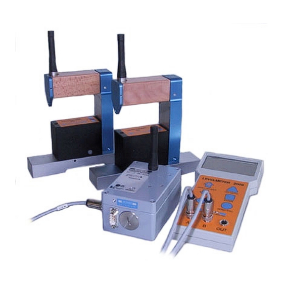
LEVELTRONIC NT and MINILEVEL NT
File: „nt_funke.doc"
O
PERATOR
with
Radio transmission
and
LEVELMETER 2000
Tel.
0041 (0) 52 233 66 66
Fax.
0041 (0) 52 233 20 53
Homepage: http://www.wylerag.com
E-Mail:
wyler@wylerag.com
'
M
S
ANUAL
April 24/.2000


Need help?
Do you have a question about the LEVELTRONIC NT and is the answer not in the manual?
Questions and answers