Advertisement
Quick Links
Download this manual
See also:
Operator's Manual
Advertisement

Related Manuals for WYLER LEVELMETER 2000


Summary of Contents for WYLER LEVELMETER 2000
- Page 1 WYLER AG Tel. 0041 (0) 52 233 66 66 Im Hölderli Fax. 0041 (0) 52 233 20 53 CH-8405 WINTERTHUR Switzerland Homepage: http://www.wylerag.com E-Mail: wyler@wylerag.com ANUAL LEVELMETER2000 HE CONVENIENT INSTRUMENT ZEROTRONIC-SENSORS MINILEVEL / LEVELTRONIC NT...
- Page 2 Short description of panel functions 2.2. Panel/Functions LEVELMETER 2000 OW TO USE THE 3.0. Functions of Levelmeter 2000 used with ZEROTRONIC sensors, MINILEVEL and LEVELTRONIC NT with/without radio transmission 3.1. Checking the functions 3.2. ZERO-Setting / ZERO absolute and ZERO virtual 3.3.
- Page 3 Default values, basic standards Description of panel functions Description of the CLINO 2000 Description of the panel 2.2.2 Direction of the inclination 2.2.2 Disabling the automatic shut-off of the LEVELMETER 2000 2.1.2.2 Display and panel 2.1.1 ENTER key 2.1.1 ENTER key 2.2.1...
- Page 4 Measuring range Measuring unit 2.1.1 Measuring units 2.2.2 Measuring units MINILEVEL NT Mounting of the sensors / codes 2.1.2 ON/MODE key 2.1.1 ON/MODE key 2.2.1 Panel and display 2.1.1 Panel/Functions PIN definition / Connector Port for power supply 2.1.1 Port for RS232 or for power supply 2.1.1 Ports for sensors/instruments 2.1.1...
-
Page 5: I Ntroduction
The measuring system is designed to be completely antimagnetic. The basic signal received in the LEVELMETER 2000 will be computed into an angle by comparing the signal with a reference curve stored and then displayed in the required unit. -
Page 6: Possible Configurations (Instruments And Sensors Connections)
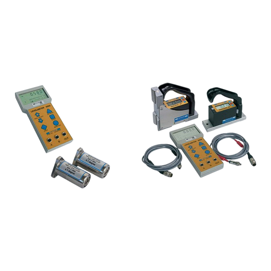
On both of the ports ( A & B) up to 31 sensors/instruments may be connected. This manual covers mainly the combination of the LEVELMETER 2000 with ZEROTRONIC sensors. For other possible combinations such as together with the instruments MINILEVEL and LEVELTRONIC NT please refer to the respective manuals. -
Page 7: Short Description Of Panel Functions
TARTING LEMENTS OF PANEL 2.1. Short description of panel functions 2.1.1. Panel and display Ports Main display Sensor address Measuring unit Battery-Display Selection pointer / Mode Key ON/MODE Key ZERO/SELECT Key ENTER Key HOLD Key SEND/ESC 2 Ports for sensors/instruments Serial port RS232 or external power supply Page 7 of 31 Pages... - Page 8 ON/MODE key for more than 3 seconds the display starts flashing and the automatic shut off is disabled. In the standard mode the instrument shut off after about 10 minutes. Exeption: In case the LEVELMETER 2000 is powered by a connection to a mains adapter, the instrument is never shutting off automatically.
-
Page 9: Hold-Function
In the standard mode the instrument shut off after about 10 minutes. Exeption: In case the LEVELMETER 2000 is powered by a connection to a mains adapter, the instrument is never shutting off automatically. Function - 2 - ON/MODE is also used for moving the selection pointer on the lower display area. -
Page 10: Measuring Range
With the HOLD key a measured value may „frozen“. This value will be displayed until by pressing the key SEND the LEVELMETER 2000 will return to the measuring mode. Function - 2 - When using the mode REL ZERO and ZERO the actual measuring value can be... - Page 11 2.2.2. Description of the panel Main display The actual measuring values of an active sensor/instrument are displayed. By using the mode SENSOR the other connected sensors/instruments may be chosen for display. Indicator of The pictograph indicates the direction of the inclination inclination direction declining to the right (negative angle)
- Page 12 LEVELMETER 2000 OW TO USE THE 3.0. Functions of Levelmeter 2000 used with ZEROTRONIC sensors, MINILEVEL and LEVELTRONIC NT with/without radio transmission Page 12 of 31 Pages...
-
Page 13: E Rror Messages
Both keys ON/MODE and ENTER must be pressed simultaneously for at least one second. All the manually installed data is lost and the LEVELMETER 2000 will be set to the following basic standards: Basic standards (Default values): Measuring mode: absolute... - Page 14 The LEVELMETER 2000 should have been turned on a few minutes before the measurement procedure. For this procedure a suitable surface must be chosen (rigid, flat and as horizontal as possible).
- Page 15 Only one sensor at a time can be set to ZERO virtual. This sensor must be selected first. The selection pointer must be moved below the marking ZERO in the display of the LEVELMETER 2000 by pressing the key ON/MODE several times.
- Page 16 In these cases it is useful to set the basic value for this surface to: 0°00’00‘‘ This can be done by manually setting the virtual zero as described before or by automatically define the value with the Levelmeter 2000 set-up. (It is done by using a reversal measurement mode without turning the sensor 180 deg.)
- Page 17 Result: Despite the fact that the sensor is still mounted at the same angle the display of the Levelmeter 2000 now shows the value 0°00‘00‘‘ This is the so called virtual ZERO This new virtual ZERO is the reference for all the future measurements based on this angle (originally 0°09‘16‘‘)
- Page 18 3.3. Selection of the measuring unit The desired measuring unit can be selected by repeatedly pressing the key ON/MODE until the selection pointer is below the function UNIT and then the ENTER is pressed. The possible formats may now be chosen by pressing the key ZERO/SELECT "+/-"...
- Page 19 HOLD function has not been successfully completed within 60 seconds. The procedure needs to be repeated. By using the function RESET the LEVELMETER 2000 will return to the standard settings. With the exception of the calibration data all previous adjustments are lost!! RESET After the new software is loaded an instrument’s reset must be done.
- Page 20 3.5. Function SEND (Print-Function) Using the key SEND/ESC will send the displayed value through the port "OUT" to a connected PC, or Laptop via the RS232 port. This function can also be used in combination with HOLD in order to transmit the „frozen“ value.
- Page 21 (Example is WIN NT) 1. Open the Terminal-Program in Windows / Accessories. and insert a name Confirm with OK 2. Enter the serial port definition connected to the Levelmeter 2000. Confirm with OK 3. Enter the parameters Bits per Second: 9600 Data bits:...
- Page 22 One sensor with address 50 is connected to port "A" Meaning of the display: Continuous number. (3 measurements per second are performed) A050 Port „A“, address 50 - 0.000100 Rad -0.000100 respectively - 100 µRad One sensor with address 50 is connected to port "A", one sensor with address 21 is connected to port "B"...
- Page 23 3.7. Selecting a sensor or an instrument With the LEVELMETER 2000 the possibility exists to display the measured values of individual sensors, respectively instruments connected, or the difference between two connected sensors. In case of the differential measurement the two sensors must be connected to the two ports A and B. It is not possible to measure the difference of two sensors connected to the same port.
- Page 24 This value can be accepted or a new value can be entered or the value can be set to zero. is temporarily stored in the Levelmeter 2000 in case of differential measurement with two sensors / measuring instruments. The „REL ZERO OFFSET“ value can be changed during the measurement.
- Page 25 ENTER. In the display the existing value is seen. By pressing the key ON/MODE the value will be set to "0". This can now be confirmed with ENTER and the Levelmeter 2000 starts in the measuring mode. The stack is empty. Page 25 of 31 Pages...
- Page 26 ON/MODE. If reached it needs to be accepted by pressing ENTER. In the display of the LEVELMETER 2000 a possible installed lower limit is displayed with a marking LO. This value may now manually be adjusted to the required value by using ZERO/SELECT „+/-“.
- Page 27 Remarks: The rechargeable batteries are automatically charged when an external power supply is connected The regular batteries can stay in the LEVELMETER 2000 when an external power supply is connected as they will automatically be shut off. 4.2.
- Page 28 ERVICE 6.1. General The LEVELMETER 2000 needs no special service other than the regular cleaning. 6.2. Storage / Care and handling of the batteries Read the instructions in your manual before installing batteries. Make sure to insert the batteries properly, following the symbols showing you the correct way to position the positive (+) and negative (-) ends of the batteries.
- Page 29 6.3. Spare parts The following spares are available: - Batteries, rechargeable batteries - Stand with connection to external power supply - Cables 6.4. Changing of sensor address Only the one sensor which address must be changed is allowed to be connected either on port A or B. Move the position indicator to the position ADDRESS by repeatedly pressing the key ON/MODE and confirm the setting with...
- Page 30 The LEVELMETER 2000 offers the possibility by superimposed 3-point calibration to impair the calibration curves stored in the Sensor. This corrective interference we call “Quick Calibration”. Quick Calibration can be executed on ZEROTRONIC sensors.
- Page 31 The invoicing will be through the WYLER partner in your country. Please do not hesitate to make use of this service in order to have your WYLER instrument back at your disposal as soon as possible. In case of any questions please contact WYLER SWITZERLAND or your local distributor, we will gladly help you to use the ERS successfully.
Need help?
Do you have a question about the LEVELMETER 2000 and is the answer not in the manual?
Questions and answers