Advertisement
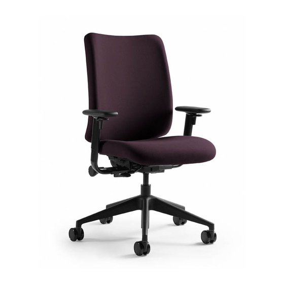
Crew Task Chair - Components for Customer Service
Table of Contents
Page
Topic
2
3-4
5
6-7
8
9-10
11
12
13
14-15
16
©
2006 Steelcase Inc.
Grand Rapids, MI 49501 U.S.A.
Printed in U.S.A.
R
#2 PHILLIPS BIT
3/16
ALLEN
T-30
Page 1 of 16
939500070 Rev E
Advertisement
Table of Contents

Subscribe to Our Youtube Channel
Related Manuals for Turnstone Crew Task Chair


Summary of Contents for Turnstone Crew Task Chair
-
Page 1: Table Of Contents
Crew Task Chair - Components for Customer Service Table of Contents Page Topic Replacement of Casters Replacement of Pneumatic Cylinder Replacement of Foot Ring Replacement of Back Assembly Replacement of Adjustable Height Insert & Spring 9-10 Replacement of Seat-Slide Assembly... -
Page 2: Replacement Of Casters
Replacement of Casters Gently rest the chair on its back. Pull/wiggle the casters out. (Pry with a screwdriver, if additional force is required. Take care to not damage surfaces.) Push the new casters in. This should take minimal force. CAUTION: Do not put your fingers between the base and the new caster while installing. -
Page 3: Replacement Of Pneumatic Cylinder
Replacement of Pneumatic Cylinder Extend chair to the highest seating position. Turn chair upside down or on its side. Hold one of the legs of the five star base with one hand. Hit the bottom of the cylinder with a non-marring hammer. Install the pneumatic cylinder removal tool (part number 879100100) on the top part of the cylinder, as close as possible... - Page 4 Replacement of Pneumatic Cylinder (Continued) To install new Pneumatic Cylinder Insert new cylinder into chair (5a). Lightly tap once with a non-marring hammer (5b). Set chair with new cylinder into the base of the chair. Adjust height to ensure the pneumatic cylinder is aligned properly.
-
Page 5: Replacement Of Foot Ring
Replacement of Foot Ring Extend chair to the highest seating position. Turn chair upside down or on its side. Hold one of the legs of the five star base with one hand. Hit the bottom of the cylinder with a non-marring hammer. Turn the foot ring as shown and remove the old foot ring. -
Page 6: Replacement Of Back Assembly
Replacement of Back Assembly NOTE: Removal of the back will require two (2) people. Raise back as far as it will go. Under the backrest there are two white plastic teeth visible, these are what need to be pushed forward to release the back. - Page 7 Replacement of Back Assembly (Continued) Slide new back assembly onto the chair while lightly pulling height adjustment levers forward (4a), then align with mechanism and push down (4b). Release adjustment levers (4c). Page 7 of 16 939500070 Rev E...
-
Page 8: Replacement Of Adjustable Height Insert & Spring
Replacement of Adjustable Height Insert & Spring Apply downward pressure to the seat. ASSEMBLY SPRING Squeeze and hold arm height adjustment lever. Lower arm to the lowest position and quickly jerk up on the arm assembly to disengage arm assembly from chair. SPRING Remove and dispose of the old spring and insert. -
Page 9: Replacement Of Seat-Slide Assembly
Replacement of Seat-Slide Assembly Gently rest chair on its back. Remove eight (8) torx drive screws. Remove seat slide handle guards and seat slide handle brackets. SEAT SLIDE HANDLE GUARD SEAT SLIDE HANDLE BRACKET = Spring Locations = Screw Locations Page 9 of 16 939500070 Rev E... - Page 10 SEAT SLIDE Replacement of HANDLE Seat-Slide Assembly (Continued) Remove seat slide handle. Remove springs. Remove seat retainers. SPRING Determine which screws you have that attach the seat slide handle guards and seat retainers: INTERMEDIATE TORX DRIVE PHILLIPS DRIVE WASHER HEAD PAN HEAD TORX DRIVE = Spring Locations...
-
Page 11: Replacement Of Seat Assembly
NOTE: The rods need Replacement of Seat to slide through the Assembly opening in the seat pan. Remove hardware from seat by performing steps 1 through 6 on pages 8 and 9. Remove seat by tilting the front of the seat towards the base of the chair (2a). -
Page 12: Replacement Of Arm Assembly
Replacement of Arm Assembly Remove seat assembly (see page 9). Remove the four (4) screws. (Use a 1/2" wrench to prevent the T-Nut, if present, from spinning.) Remove old arm assembly. Mount new arm. Attaching with the screws. Ensure the arm is square with the back and then tighten the screws. -
Page 13: Replacement Of Arm Caps
Replacement of Arm Caps If your chair has adjustable arms, remove the height adjustment lever, it should come off by hand, if not use a 1/2" wrench, or similar, to pry it and wiggle it the rest of the way off. Remove the Phillips screw. -
Page 14: Replacement Of Arm Toggle
Replacement of Arm Toggle Loosen cam lock lever and push the arm in all the way to align the hole in the arm assembly with the allen screw head. Using a 3/16" allen wrench, remove screw and the lever and other related hardware. - Page 15 Replacement of Arm Toggle (Continued) Install pivot pin into the cam lock lever. Turn the lever with pivot pin installed onto the screw. CAM LOCK LEVER Adjust screw so that cam lock lever tightens and loosens the arm tube. PIVOT PIN Adjust arms to user preference and tighten the lever.
-
Page 16: Replacement Of Chair Control
Replacement of Chair Control Remove the seat assembly by performing steps 1 and 2 on page 10. Remove the seat back by performing steps 1 through 3 on pages 6 and 7. If applicable, remove the arm assembly by performing steps 1 through 3 on page 11. Remove the pneumatic cylinder from the control by performing steps 1 through 4 on page 3.
Need help?
Do you have a question about the Crew Task Chair and is the answer not in the manual?
Questions and answers