Advertisement
Table of Contents
- 1 Package Checklist
- 2 Mounting Dimensions (Unit = MM)
- 3 DIN-Rail Mounting
- 4 ATEX Information
- 5 Wiring Requirements
- 6 Grounding the Ethernet Switch
- 7 Wiring the Redundant Power Inputs
- 8 Communication Connections
- 9 Redundant Power Inputs
- 10 DIP Switch Settings
- 11 Led Indicators
- 12 Switching, Filtering, and Forwarding
- 13 Switching and Address Learning
- 14 Auto-Negotiation and Speed Sensing
- 15 Specifications
- Download this manual
Ethernet Switch – Basic Line
IE-SW-BL05/08 Series
Hardware Installation Guide
Third Edition, October 2012
1243320000/02/10.12
Please note:
This document and any further product information - if
available - can be downloaded at the internet link:
http://www.weidmueller.com/downloads
Copyright Notice
Copyright 2012 Weidmüller Interface GmbH & Co. KG
All rights reserved.
Reproduction without permission is prohibited.
Advertisement
Table of Contents

Related Manuals for Weidmuller IE-SW-BL05 Series


Summary of Contents for Weidmuller IE-SW-BL05 Series
- Page 1 Ethernet Switch – Basic Line IE-SW-BL05/08 Series Hardware Installation Guide Third Edition, October 2012 1243320000/02/10.12 Please note: This document and any further product information - if available - can be downloaded at the internet link: http://www.weidmueller.com/downloads Copyright Notice Copyright 2012 Weidmüller Interface GmbH & Co. KG All rights reserved.
-
Page 2: Package Checklist
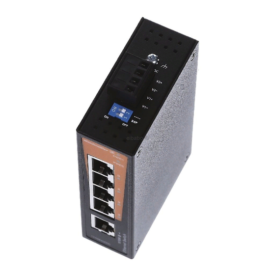
Ethernet Switch Hardware Installation Guide Features High Performance Network Switching Technology IE-SW-BL05 series: 10/100BaseT(X) (RJ45), 100 BaseFX (SC/ST connector, multi/single-mode) IE-SW-BL08 series: 10/100BaseT(X) (RJ45), 100 BaseFX (SC/ST connector, multi/single-mode) 10/100M, Full/Half-Duplex, MDI/MDIX auto-sensing ... - Page 3 Panel Layout of IE-SW-BL05-5TX / IE-SW-BL08-8TX IE-SW-BL08 IE-SW-BL05 Grounding screw Front Panel View Front Panel View Terminal block for power input P1/P2 Heat dissipation orifices DIP Switches Power input P1 LED Power input P2 LED 10/100BaseT(X) Port TP port’s 10/100 Mbps Article Number 10.
- Page 4 Panel Layout of IE-SW-BL05-4TX-1SC/ST IE-SW-BL05-4TX-1ST IE-SW-BL05-4TX-1SC Grounding screw Front Panel View Front Panel View Terminal block for power input P1/P2 Heat dissipation orifices DIP Switches Power input P1 LED Power input P2 LED 10/100BaseT(X) Port TP port’s 10/100 Mbps Article Number 10.
- Page 5 Panel Layout of IE-SW-BL08-6TX-2SC/ST IE-SW-BL08-6TX-2ST IE-SW-BL08-6TX-2SC Grounding screw Front Panel View Front Panel View Terminal block for power input P1/P2 Heat dissipation orifices DIP Switches Power input P1 LED Power input P2 LED 10/100BaseT(X) Port TP port’s 10/100 Mbps Article Number 10.
-
Page 6: Mounting Dimensions (Unit = Mm)
Mounting Dimensions (unit = mm) - 6 -... -
Page 7: Din-Rail Mounting
DIN-Rail Mounting The aluminum DIN-rail attachment plate should already be fixed to the back panel of the Ethernet Switch when you take it out of the box. If you need to reattach the DIN-rail attachment plate, make sure the stiff metal spring is situated towards the top, as shown in the figures below. -
Page 8: Wiring Requirements
Wiring Requirements WARNING Safety First! Turn the power off before disconnecting modules or wires. The correct power supply voltage is listed on the product label. Check the voltage of your power source to make sure that you are using the correct voltage. Do use a voltage greater than what is specified on the product label. -
Page 9: Wiring The Redundant Power Inputs
Wiring the Redundant Power Inputs The top two contacts and the bottom two contacts of the 4-contact terminal block connector on the Ethernet Switch’s top panel are used for the Ethernet Switch’s two AC/DC inputs. Top and front views of one of the terminal block connectors are shown here. - Page 10 RJ45 (8-pin) to RJ45 (8-pin) Straight-Through Cable Wiring RJ45 (8-pin) to RJ45 (8-pin) Cross-Over Cable Wiring 100BaseFX Ethernet Port Connection The concept behind the SC/ST port and cable is quite straightforward. Suppose you are connecting devices I and II; contrary to electrical signals, optical signals do not require a circuit in order to transmit data.
-
Page 11: Redundant Power Inputs
Redundant Power Inputs Both power inputs can be connected simultaneously to live AC/DC power sources. If one power source fails, the other live source acts as a backup, and automatically supplies all of the Ethernet Switch’s power needs. DIP Switch Settings IE-SW-BL05/08 DIP Switches The default setting for each DIP Switch is OFF. -
Page 12: Switching, Filtering, And Forwarding
Auto MDI/MDI-X Connection The Auto MDI/MDI-X function allows users to connect the Ethernet Switch’s 10/100BaseTX ports to any kind of Ethernet device, without needing to pay attention to the type of Ethernet cable being used for the connection. This means that you can use either a straight-through cable or cross-over cable to connect the Ethernet Switch to Ethernet devices. -
Page 13: Specifications
Specifications Technology Standards IEEE 802.3 for 10BaseT, IEEE 802.3u for 100BaseT(X) and 100BaseFX, IEEE 802.3x for Flow Control Processing Type Store and Forward Flow Control IEEE 802.3x flow control, back pressure flow control Interface RJ45 Ports 10/100BaseT(X) auto negotiation speed, F/H duplex mode, and auto MDI/MDI-X connection Fiber Ports 100BaseFX ports (SC/ST connector,... - Page 14 Environmental Limits Operating Temperature -10 to 60°C (14 to 140°F) -40 to 75°C (-40 to 167°F) for -T models Storage Temperature -40 to 85°C (-40 to 185°F) Ambient Relative Humidity 5 to 95% (non-condensing) Regulatory Approvals Safety UL508 Hazardous Location UL/cUL Class I, Division 2, Groups A, B, C, and D;...
Need help?
Do you have a question about the IE-SW-BL05 Series and is the answer not in the manual?
Questions and answers