Advertisement
Quick Links
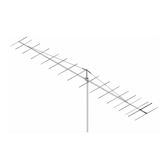
SPECIFICATIONS:
Model ......................................... 2M5WL
Frequency Range ....................... 144 To 148 MHz
*Gain .......................................... 16.84 dBi
Front to back .............................. 22 dB Typical
Beamwidth ............................... E=26° H=29°
Feed type ................................... "T" Match
Feed Impedance. ....................... 50 Ohms Unbalanced
Maximum VSWR ........................ 1.2:1
Input Connector .......................... "N" Female
FEATURES:
The 2M5WL is designed with the SERIOUS "Weak Signal" enthusiast in mind. It provides excellent gain for min-
imum weight and wind load yet is strong enough to survive 100+ mph winds. The modified folded dipole driven element is
also unique as it's center is a CNC machined block of aluminum fitted with 'O' ringed connectors and access cap. After
factory assembly, the block is filled with a space age silicone gel which further seals and increases dielectric breakdown
and arc-over protection. The 3/16" rod elements mount through the boom on UV stabilized button insulators. All hardware
is stainless steel except for U-bolts. A vertical riser and an overhead Dacron cord guy system is supplied for boom sup-
port. This antenna is widely used in EME (W5UN's 48 2M5WL's and many others) and large Tropo scatter arrays. Sever-
al optional items are available to provide more gain from your 2M5WL's. 2 and 4 port power dividers are available for
matching stacks of 2 or 4 antennas. 50 Ohm phasing lines model VHF-50-2M5WL2 and VHF-50-2M5WL4 can be ordered
for phasing 2 or 4 antennas together. 'H' frames, OR-2800 and MT-3000 AZ and EL rotators are also available as well as
Rohn and US towers.
M2 Antenna Systems, Inc. 4402 N. Selland Ave. Fresno, CA 93722
M2 Antenna Systems, Inc.
Model No: 2M5WL
*Subtract 2.14 from dBi for dBd
Tel: (559) 432-8873 Fax: (559) 432-3059 Web: www.m2inc.com
©2015 M2 Antenna Systems Incoporated
Power Handling .......................... 1.5 kW
Boom Length / Dia ...................... 33' / 1-1/2" to 3/4"
Maximum Element Length .......... 40-5/8"
Turning Radius: .......................... 18' 9"
Stacking Distance ....................... 14' High & 14' Wide
Mast Size .................................... 2" Nom.
Wind area / Survival ................... 2.7 Sq. Ft. / 100 MPH
Weight / Ship Wt. ........................ 13 Lbs. / 14 Lbs.
03/15/20
Advertisement

Related Manuals for M2 Antenna Systems 2M5WL


Summary of Contents for M2 Antenna Systems 2M5WL
- Page 1 This antenna is widely used in EME (W5UN’s 48 2M5WL’s and many others) and large Tropo scatter arrays. Sever- al optional items are available to provide more gain from your 2M5WL’s. 2 and 4 port power dividers are available for matching stacks of 2 or 4 antennas.
- Page 2 2M5WL ASSEMBLY MANUAL 1. Start by laying out the boom sections using the DIMENSION sheet as a guide. Use 8-32 X 1-1/4 screws and locknuts to join 3/4” to 1” sections; 1-1/2” screws for 1” to 1-1/4” sections; 1-3/4” screws for 1-1/4” to 1-1/2” and 1-1/2" to 1-1/2" sections.
- Page 3 2M5WL DIMENSION SHEET D I M E N S I O N S H E E T 2 M 5 W L E L E M E N T S P A C I N G E L E M E N T L E N G T H 4 0 .
- Page 4 Check for continuity and match across the band. It should be 1.5:1 or better from 144 to 146 MHz and then rise to about 2:1 at 148 MHz. Remember, the 2M5WL is tailored for the lower half of two meters where horizontal polarity and sideband / CW are the common modes.
- Page 5 2M5WL D.E. & OVERHEAD DETAIL REPLACE WITH EYE BOLT...
- Page 6 2M5WL PARTS & HARDWARE DESCRIPTION BOOM SECTION #1, 1 X .058 X 60” STR ......1 BOOM SECTION #2, 1-1/4 X .058 X 60” SOE ...... 1 BOOM SECTION #3, 1-1/2 X .058 X 60” SOE ...... 1 BOOM SECTION #4, 1-1/2 X .058 X 60” SBE ...... 1 BOOM SECTION #5, 1-1/4 X .058 X 60”...
Need help?
Do you have a question about the 2M5WL and is the answer not in the manual?
Questions and answers