Advertisement
Quick Links
SPECIFICATIONS:
Model ......................................... 215-470LP16
Frequency Range ....................... 215-470 MHz Cont.
*Gain .......................................... 8.5 dBi Typical Average
Front to back .............................. 27 dB Typical Average
Beamwidth.................................. @230MHz E=61°/H=92°
Beamwidth.................................. @350MHz E=58°/H=89°
Beamwidth.................................. @450MHZ E=59°/H=90°
Feed Impedance. ....................... 50 Ohms Unbalanced
FEATURES:
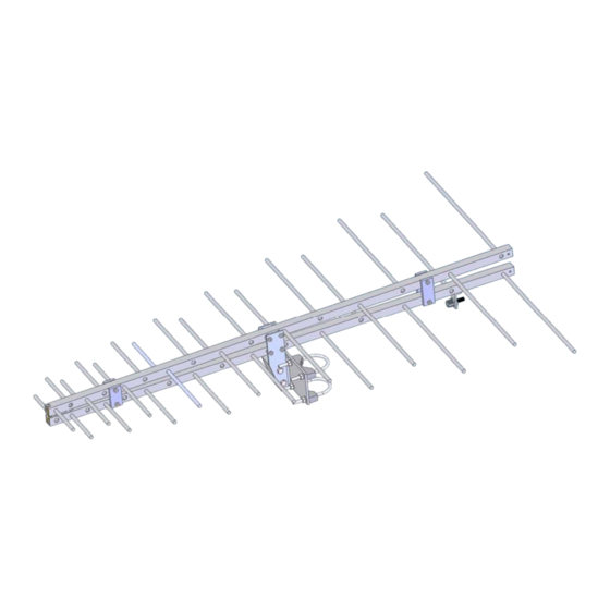
The 215-470LP16 is a dual boom log periodic with more elements than many conventional designs. The extra
elements help in lowering VSWR and produces higher gains across the working frequency range. The result is a high
quality commercial broad band VHF antenna. Built for extreme environmental conditions, this design uses 6061-t6 alumi-
num and all stainless hardware and UV stabilized acetyl insulation. Internal stainless screws secure the elements in
place. Optional models are available with welded elements for corrosive environments or extreme conditions. The 215-
470LP16 antenna can be ordered with many finishes, anodized, chem filmed, or a combination chem film and paint, with
many colors available.
M2 Antenna Systems, Inc.
Model No: 215-470LP16
*Subtract 2.14 from dBi for dBd
M2 Antenna Systems, Inc. 4402 N. Selland Ave. Fresno, CA 93722
Tel: (559) 432-8873 Fax: (559) 432-3059 Web: www.m2inc.com
©2015 M2 Antenna Systems Incorporated
Maximum VSWR ........................ >1.5:1 AVG.
Mounting Polarity ........................ Horizontal or Vertical
Mast ............................................ 1.5-2.0 Dia
Input Connector .......................... "N" Female
Power Handling .......................... 250 Watts
Boom Length / Dia. ..................... 42" / 3/4" SQ
Turning Radius: .......................... 21"
Wind area / Survival ................... 0.8 Sq. Ft. / 125 MPH
Weight / Ship Wt. ........................ 14 lbs. / 16 lbs.
09/23/15
Rev.00
Advertisement

Subscribe to Our Youtube Channel
Related Manuals for M2 Antenna Systems 215-470LP16


Summary of Contents for M2 Antenna Systems 215-470LP16
- Page 1 *Subtract 2.14 from dBi for dBd FEATURES: The 215-470LP16 is a dual boom log periodic with more elements than many conventional designs. The extra elements help in lowering VSWR and produces higher gains across the working frequency range. The result is a high quality commercial broad band VHF antenna.
- Page 2 215-470LP16 DIMENSION SHEET...
- Page 3 215-470LP16 HORIZONTAL MOUNTING HORIZONTAL MOUNTING TO A VERTICAL MAST USING THE SIDE MOUNT OPTION WHEN ATTACHING U-BOLT AND UNICRADLE USE SIDE HOLES ON MAST MOUNTING PLATE WITH HORIZONTAL MOUNTING THE FEED LINE CAN BE ATTACHED TO THE LOWER BOOM SECTION AND DOWN...
- Page 4 215-470LP16 VERTICAL MOUNTING ATTACH THE FEED LINE TO THE REAR BOOM CABLE SUPPORT FOR STRAN RELIEF OF THE CABLE AND CONNECTOR. NOTE THE POSITION OF THE CONNECTOR MOUNTING BRACKET, IT IS MOVED TO THE REAR OF THE CABLE ACCESS SLOT...
- Page 5 215-470LP16 ASSMBLY 1. Find the lower boom assembly with the cable access slot. Add the con- nector mount bracket. Refer to the horizontal or vertical mounting options pages to chose connector mount bracket location. 2. locate the Feedline RG-303 with connectors. Feed the SMA female con- nector end of the cable inside the boom starting from the cable access slot.
- Page 6 215-470LP16 ASSMBLY 3. Note the picture of the feed nose assembly, locate the grounded side of the feed nose assembly. Warning The feed nose assembly when unattached is fragile, after complete installation it will be very durable. Care must be taken during the following steps.
- Page 7 215-470LP16 ASSMBLY 5. Carefully slide the cable and feed nose assembly back into the boom assembly, align the grounded side of the feed nose assembly with the hole in the front of the boom assembly and add the 8-32 x 3/8 screw.
- Page 8 215-470LP16 ASSMBLY 6. locate the front and rear delrin spreader bars. Add the both smaller front spreader bars to either side of the boom assembly add the 8-32 screw thru the boom and add the nut. Repeat for the rear end of the boom as- sembly.
- Page 9 215-470LP16 ASSMBLY 8. Locate the BTM side plate, BTM block and mast mount plate. See the picture and assemble the BTM bracket. Add the u-bolts and uni-cradles for your mounting style, horizontal or vertical polarity. Be sure to tighten all hardware before installation. Always use good low loss coax for feed line.
- Page 10 215-470LP16 PARTS & HARDWARE DESCRIPTION ................QTY BOOM ASSEMBLY W/ ELEMENTS, UPPER ........ 1 BOOM ASSEMBLY W/ ELEMENTS, LOWER ....... 1 FEED NOSE ASSEMBLY .............. 1 FEED LINE, RG-303 W/ SMA FEMALE TO N FEMALE ....1 CONNECTOR MOUNT BRACKET ..........1 REAR BOOM CABLE SUPPORT ..........
Need help?
Do you have a question about the 215-470LP16 and is the answer not in the manual?
Questions and answers