Table of Contents
Advertisement
Quick Links
SPECIFICATIONS:
Model ......................................... 222XP30
Frequency Range ....................... 222 To 226 MHz
*Gain .......................................... 17.4 dBi
Front to back .............................. 21 dB Typical
Beamwidth ............................... E=23° H=25°
Feed type ................................... "T" Match
Feed Impedance. ....................... 50 Ohms Unbalanced
Maximum VSWR ........................ 1.2:1 Typical
Input Connector .......................... "N" Female
FEATURES:
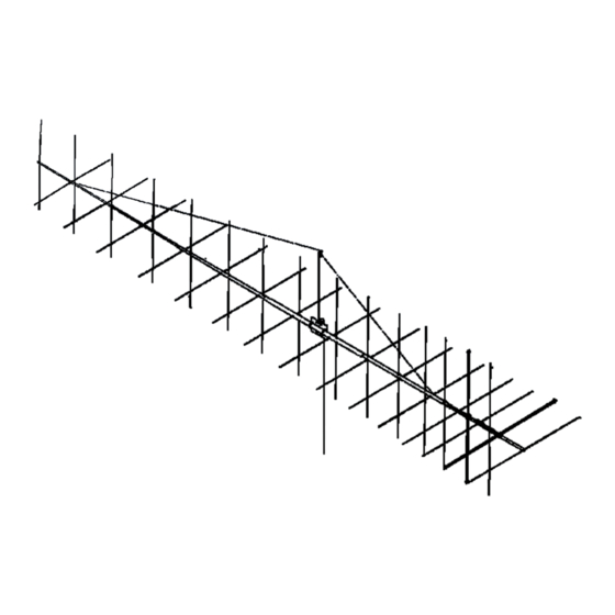
The 222XP30 is the dual polarized version of the famed 222-5WL 15 element Yagi. It is our latest design using
computer techniques to allow maximum gain and patterns in both the horizontal and vertical planes. The vertical elements
have been shifted 1/4 wave length in front of the horizontal set to allow circular polarization if needed. This means four
possible polarization modes with one antenna! Two antennas stacked are a dynamite DX package for FM and SSB and 4
or more are perfect for long haul tropo DXing or moonbounce. The 222XP30 allows you to experience the radio
spectrum's best tropo frequency without bustin' your mast or your budget!
Structurally the 222XP30 is sturdy and clean. Elements are 3/16" 6061-T6 aluminum rod mounted through the
boom on UV stabilized "button" insulators. The boom is a full 1-1/2 inch diameter in the middle tapering through two 1-1/4
inch sections to stiff 1 and 3/4 inch tips. The main 'N' connectors are O-ring sealed to the CNC machined block and 4:1
balun connectors feature triple seals. The internal module connections are sealed in a space-age silicone gel.
M2 Antenna Systems, Inc. 4402 N. Selland Ave. Fresno, CA 93722
M2 Antenna Systems, Inc.
Model No: 222XP30
*Subtract 2.14 from dBi for dBd
Tel: (559) 432-8873 Fax: (559) 432-3059 Web: www.m2inc.com
©2015 M2 Antenna Systems Incoporated
Power Handling .......................... 1.5 kW
Boom Length / Dia ...................... 24' 3" / 1-1/2" To 3/4"
Maximum Element Length .......... 25-7/8"
Turning Radius: .......................... 13" 10"
Stacking Distance ....................... 120" High & 120" Wide
Mast Size .................................... 1-1/2" to 2" Nom.
Wind area / Survival ................... 2.4 Sq. Ft. / 100 MPH
Weight / Ship Wt. ........................ 12 Lbs. / 13 Lbs.
05/28/15
Rev.01
Advertisement
Table of Contents

Related Manuals for M2 Antenna Systems 222XP30


Summary of Contents for M2 Antenna Systems 222XP30
- Page 1 *Subtract 2.14 from dBi for dBd FEATURES: The 222XP30 is the dual polarized version of the famed 222-5WL 15 element Yagi. It is our latest design using computer techniques to allow maximum gain and patterns in both the horizontal and vertical planes. The vertical elements have been shifted 1/4 wave length in front of the horizontal set to allow circular polarization if needed.
- Page 2 222XP30 ASSEMBLY MANUAL Tools required: slot screwdriver, 11/32”, 7/16”, and 1/2” end wrenches and / or sockets. 1. Start by laying out the boom sections using the DIMENSION sheet as a guide. Use the appropriate 8-32 screws and locknuts as shown to join the sections. To make the assembly easier, support the completed boom about waist high on bucks, tables, etc.
- Page 3 222XP30 ASSEMBLY MANUAL 10. If you have not already done so, attach the boom to mast plate to the boom. It is normally mounted at the balance point, as shown on the DIMENSION SHEET. Since the feed line represents significant weight it is best to have it, or a temporary equivalent, attached and fastened along the boom with cable ties before final mounting the plate.
- Page 4 222XP30 ASSEMBLY MANUAL 13. Install the two turnbuckles into the fiberglass rod mast clamp assembly as shown above in the figure. Adjust threads until just one or two show inside turnbuckle body. With two friends, lift up the two ends of the boom until the middle is 4” to 6” LOWER than the ends. Attach one end of the Dacron cord to the rear U clip by taking two wraps through the “U”...
- Page 5 222XP30 DIMENSION SHEET...
- Page 6 222XP30 PARTS & HARDWARE DESCRIPTION BOOM, 3/4 X .049 X 18” ALUM. TUBE ........ 1 BOOM, 1.0 X .058 X 51” ALUM. TUBE ........ 1 BOOM, 1.0 X .058 X 57” ALUM. TUBE ........ 1 BOOM, 1-1/4 X .058 X 60 SOE, ALUM........ 2 BOOM, 1-1/2 X .058 X 60 SBE ALUM.
Need help?
Do you have a question about the 222XP30 and is the answer not in the manual?
Questions and answers