Advertisement
SPECIFICATIONS:
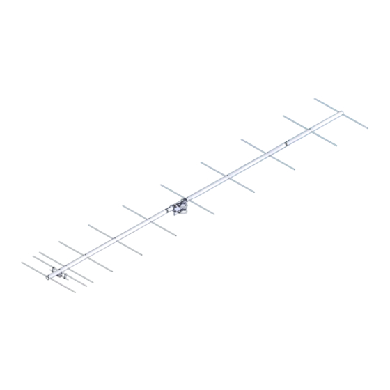
Model ......................................... 235-11
Frequency Range ....................... 230 To 240 MHz
*Gain .......................................... 15.07 dBi
Front to back .............................. 23 dB Typical
Beamwidth ............................... E=30 deg. H=35 deg.
Feed type ................................... "T" Match
Feed Impedance. ....................... 50 Ohms Unbalanced
Maximum VSWR ........................ 1.5:1 Max
Input Connector .......................... "N" Female
FEATURES:
Performance has been computer optimized to meet your application. Physical construction
emphasizes long term electrical and mechanical durability. Elements are rod 5/16" 6061-T6 alumi-
num, grounded to the boom. The driven element "T" Match uses a CNC machined central block with
O-ring sealed connectors. Internal connections are encapsulated in a silicone gel with a dielectric
strength 3.7 times greater than air for enhanced power handling. Balun connectors are triple O-ring
sealed to the coax.
M2 Antenna Systems, Inc. 4402 N. Selland Ave. Fresno, CA 93722
M2 Antenna Systems, Inc.
Model No: 235-11
*Subtract 2.14 from dBi for dBd
Tel: (559) 432-8873 Fax: (559) 432-3059 Web: www.m2inc.com
©2015 M2 Antenna Systems Incorporated
Power Handling .......................... 1200W
Boom Length / Dia ...................... 141" / 1-1/2"
Maximum Element Length .......... 25-3/4"
Turning Radius: .......................... 80"
Stacking Distance ....................... 84" High & 80" Wide
Mast Size .................................... 1-1/2" to 2" Nom.
Wind area / Survival ................... 1.1 Sq. Ft. / 100 MPH
Weight / Ship Wt. ........................ 8 Lbs. / 13 Lbs.
09/30/15
Rev.00
Advertisement
Table of Contents

Subscribe to Our Youtube Channel
Related Manuals for M2 Antenna Systems 235-11


Summary of Contents for M2 Antenna Systems 235-11
- Page 1 O-ring sealed connectors. Internal connections are encapsulated in a silicone gel with a dielectric strength 3.7 times greater than air for enhanced power handling. Balun connectors are triple O-ring sealed to the coax. M2 Antenna Systems, Inc. 4402 N. Selland Ave. Fresno, CA 93722 Tel: (559) 432-8873 Fax: (559) 432-3059 Web: www.m2inc.com 09/30/15 ©2015 M2 Antenna Systems Incorporated...
- Page 2 235-11 ASSEMBLY MANUAL TOOLS REQUIRED: Screwdriver, 11/32 wrench, socket or spintite, a 7/16" and 1/2" wrench or socket, tape measure. For best results please review instructions before assembly. 1. Assemble the boom (SEE DIMENSION SHEET). 2. Install the boom to mast plate with two 2” U-bolts and cradles, placing it at about 53” from the rear of the boom.
- Page 3 2M4 ASSEMBLY MANUAL 235-11 DIMENSION SHEET...
- Page 4 235-11 DRIVEN ELEMENT DETAIL NOTE: TUCK BALUN INTO REAR OF BOOM AS SHOWN BELOW. SECURE WITH TAPE OR NYLON TIES.
- Page 5 235-11 BOOM TO MAST PLATE DETAIL...
- Page 6 2M4 ASSEMBLY MANUAL 235-11 PARTS & HARDWARE DESCRIPTION BOOM SECTION #1, 1-1/2” X .058 X 60” SOE ............1 BOOM SECTION #2, 1-1/2” X .058 X 60” SOE ............1 BOOM SECTION #3, 1-1/2” X .058 X 27” ............... 1 ELEMENT ROD, 5/16”...
Need help?
Do you have a question about the 235-11 and is the answer not in the manual?
Questions and answers