Advertisement
SPECIFICATIONS:
Model ......................................... 2M7X
Frequency Range ....................... 144 To 148 mHz
*Gain .......................................... 12.3 dBi
Front to back .............................. 20 dB Typical
Beamwidth ............................... E=43° H=50°
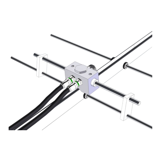
Feed type ................................... "T" Match
Feed Impedance. ....................... 50 Ohms Unbalanced
Maximum VSWR ........................ 1.2:1 Typical
Input Connector .......................... "N" Female
FEATURES:
M2 is always trying to design and build new antennas to fit the needs of amateur radio operators. The "X" series
of antennas are all designed to keep the packaging under 48" long to minimize oversize surcharges applied by shippers.
The "X" serries antennas offer the same performance as its predecessor, but with shorter boom sections. The boom sec-
tions also have a thicker wall for added strength. A side benefit of the "X" series antenna are that they are more portable
with the smaller sections. The 2M7X replaces our very popular 2M7.
The 2M7X is a computer optimized Yagi that will outperform longer old design antennas. The 2M7 covers the
whole band with only slight performance degradation at the band edges. Side lobes are very low and it is perfect for
stacking 2 or more. Its light weight and durability make it great for portable hill topping.
The 2M7X is built for long term electrical and mechanical integrity. The CNC machined "T" Match Block features
O-ring sealed connectors and is internally sealed with a space-age silicone gel with nearly 4 times the dielectric strength
of air. Elements are 6061-T6 3/16" aluminum rod, mounted through the boom on UV stabilized button insulators. All hard-
ware is stainless steel except U-bolts. Other key electrical and mechanical parts are CNC machined for accuracy and du-
rability.
M2 Antenna Systems, Inc. 4402 N. Selland Ave. Fresno, CA 93722
M2 Antenna Systems, Inc.
Model No: 2M7X
*Subtract 2.14 from dBi for dBd
Tel: (559) 432-8873 Fax: (559) 432-3059 Web: www.m2inc.com
©2021 M2 Antenna Systems Incorporated
Power Handling .......................... 1.5 kW
Boom Length / Dia ...................... 8' 10" / 1"
Maximum Element Length .......... 40-1/2"
Turning Radius: .......................... 63-1/2"
Stacking Distance ....................... 6' 8" High & 7' 3" Wide
Mast Size .................................... 1-1/2" to 2" Nom.
Wind area / Survival ................... 0.50 Sq. Ft. / 100 MPH
Weight / Ship Wt. ........................ 3 Lbs. / 4 Lbs.
3-15-21
Rev.00
Advertisement
Table of Contents

Related Manuals for M2 Antenna Systems 2M7X


Summary of Contents for M2 Antenna Systems 2M7X
- Page 1 The 2M7X replaces our very popular 2M7. The 2M7X is a computer optimized Yagi that will outperform longer old design antennas. The 2M7 covers the whole band with only slight performance degradation at the band edges. Side lobes are very low and it is perfect for stacking 2 or more.
- Page 2 2M7X ASSEMBLY MANUAL Tools handy for assembly process: screwdriver, 11/32” spin-tite or socket, 7/16” and 1/2” end wrenches and/or sockets, measuring tape. 1. Assemble the boom sections using the 8-32 X 1-1/4 screws and locknuts. 2. Lay out the elements by length and position as shown the DIMENSION sheet. Start with the REFLECTOR (longest) element.
- Page 3 2M7X DIMENSION SHEET...
- Page 4 2M7X ASSEMBLY MANUAL 8. Install the 8-32 x 1/4” set screws (internal Allen head - tool supplied) into the SHORTING BARS. Slide the bars onto the 3/16” rod driven element tips and then onto the Driven Element Block Rods. Position the Shorting Bars as specified on the Dimension Sheet: 2-9/16” from the outer face of the block to the inner face of the bar.
- Page 5 2M7X PARTS & HARDWARE DESCRIPTION BOOM SECTION, 1 X .065 X 37-1/8” SOE (M2ABS2M7X-1) ....1 BOOM SECTION, 1 X .065 X 37-1/8” SOE (M2ABS2M7X-2) ....1 BOOM SECTION, 1 X .065 X 35-3/4” STR (M2ABS2M7X-3) ....1 ELEMENTS, 3/16 ROD X DIMENSION SHEET ........1 DRIVEN ELEMENT ASSEMBLY (SADEA2MVHF1) .......1...
Need help?
Do you have a question about the 2M7X and is the answer not in the manual?
Questions and answers