Advertisement
SPECIFICATIONS:
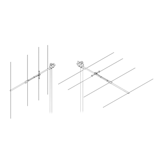
Model ......................................... 2M4
Frequency Range ....................... 144 To 148 MHz
*Gain .......................................... 9.6 dBi
Front to back .............................. 20 dB Typical
Beamwidth ............................... E=54° H=74°
Feed type ................................... "T" Match
Feed Impedance. ....................... 50 Ohms Unbalanced
Maximum VSWR ........................ 1.5:1
Input Connector .......................... "N" Female
FEATURES:
Clean mechanical design, full band coverage and computer optimized performance make the 2M4 an exceptional
antenna. A totally sealed and grounded driven element design with a unique internal balun provides the heart that will
beat for years to come. It is perfect for base and portable use, with FM, Packet or SSB. Every station needs one!!!
M2 Antenna Systems, Inc. 4402 N. Selland Ave. Fresno, CA 93722
M2 Antenna Systems, Inc.
*Subtract 2.14 from dBi for dBd
Tel: (559) 432-8873 Fax: (559) 432-3059 Web: www.m2inc.com
©2015 M2 Antenna Systems Incoporated
Model No: 2M4
Power Handling .......................... 2.5 kW
Boom Length / Dia ...................... 48" / 1"
Maximum Element Length .......... 40-1/2"
Turning Radius: .......................... 55"
Stacking Distance ....................... 66" High & 80" Wide
Mast Size .................................... 1-1/2" to 2" Nom.
Wind area / Survival ................... 0.50 Sq. Ft. / 100 MPH
Weight / Ship Wt. ........................ 3 Lbs. / 4 Lbs.
05/26/15
Rev.01
Advertisement
Table of Contents

Related Manuals for M2 Antenna Systems 2M4


Summary of Contents for M2 Antenna Systems 2M4
-
Page 1: Specifications
*Subtract 2.14 from dBi for dBd FEATURES: Clean mechanical design, full band coverage and computer optimized performance make the 2M4 an exceptional antenna. A totally sealed and grounded driven element design with a unique internal balun provides the heart that will beat for years to come. - Page 2 2M4 ASSEMBLY MANUAL Tools handy for assembly process: screwdriver, 11/32” spin-tite or socket, 7/16” and 1/2” end wrenches / sockets, measuring tape. 1. Lay out the elements by length and position as shown the DIMENSION sheet. Start with the REFLECTOR (longest) element. Balance on finger to find rough center and push on a black button insulator to about 1/2”...
- Page 3 Check for continuity and match across the rated bandwidth. C. REAR MOUNTING: The 2M4 is easily rear-mounted in either horizontal or vertical polarity. A metal mast or crossboom will have no effect on performance.
- Page 4 2M4 DIMENSION SHEET...
- Page 5 2M4 PARTS & HARDWARE Description Boom, 1 x .058 x 53" alum......... 1 Boom insert, 7/8 x .058 x 9.0" alum....1 Elements, 3/16" rod alum........4 “T” match block &1/4” rods ........ 1 BTM plate, 3 x 4 x 1/8” (M2APT0019) ....1 Balun, RG-6 ............
Need help?
Do you have a question about the 2M4 and is the answer not in the manual?
Questions and answers