Table of Contents
Advertisement
Advertisement
Table of Contents

Related Manuals for Bay Tek Games Cannonball Blast


Summary of Contents for Bay Tek Games Cannonball Blast
-
Page 2: Factory Contact Information
FACTORY CONTACT INFORMATION BAY TEK GAMES INC. Pulaski Industrial Park 1077 East Glenbrook Drive Pulaski, WI 54162 U.S.A. Our Vision: www.baytekgames.com We aspire to be the best in the world at developing and manufacturing coin JOIN SERVICE FIRST NETWORK! operated games for This free service is intended to keep you up to our customers. -
Page 3: Table Of Contents
TABLE OF CONTENTS FACTORY CONTACT INFORMATION TABLE OF CONTENTS INTRODUCTION INSPECTION DIMENSIONS AIR COMPRESSION REQUIREMENTS SAFETY PRECAUTIONS INSTALLATION COMPONENTS MAIN CABINET COMPONENTS 9/12 ASSEMBLY ISTRUCTIONS HOW TO PLAY PROGRAMMING 14/18 PREVENTATIVE MAINTENANCE SECTION TROUBLE SHOOTING 20/25 SERVICE AND REPAIR 26/28 WIRING DIAGRAMS 29/32 SCHEMATICS... -
Page 4: Introduction
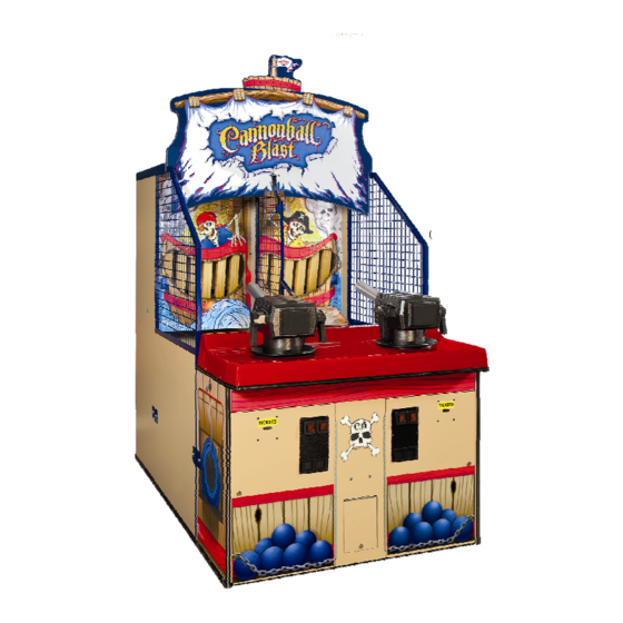
This piece is sure to serve as a great addition to your existing shooting games, and more importantly, will offer your clientele great entertainment value! We can proudly say our shooting game line up: Horse Play, Cannonball Blast & Sky Masters, is viewed as a staple in family entertainment centers across the globe. -
Page 5: Dimensions
DIMENSIONS WEIGHT Weight: 875 lbs. Shipping Weight: 1115 lbs. DIMENSIONS: 47.5” W x 100” D x 88” H (Without Stools 80” D) Order with: BAYTEK GAMES PART # AAGM-CBB... -
Page 6: Air Compression Requirements
AIR COMPRESSION REQUIREMENTS AIR COMPRESSION (supplied / built into the facility) 1. Set air pressure at the regulator for 70 PSI (4.83 bars) 2. A pneumatic air supply system, with minimum pressure of 85 PSI (5.86 bars), is required to operate this game. 3. -
Page 7: Installation Components
INSTALLATION COMPONENTS HARDWARE You will find the following pieces of hardware in a sealed bag in the cashbox. A. 1/4 – 20 x 1-1/2” Bolts B. Washers C. 5/16" Lock washers D. #10 x 5/8 Black wood screws E. #10 – 24 x 1/2” Black self-tapping screws F. -
Page 8: Main Cabinet Components
MAIN CABINET COMPONENTS REAR CABINET MIDDLE CABINET FRONT CABINET MARQUEE TICKET PLATE BOX... -
Page 9: Assembly Istructions
Assembly Instructions 1. Place the rear cabinet near or at its final location. 2. Open the rear cabinet door, uncoil the power cord and feed the cord through the hole. Uncoil other wiring cables. Do not plug the power cord into the wall outlet at this time. - Page 10 Assembly Instructions c. Install the two top rails which Install the outer metal overlap the tops of the outside screens. They are marked left screens and the rear cabinet. and right. Place the screens on Attach the front of the rails to the middle cabinet frame and the screens using 4 black push tight up again the rear...
- Page 11 Assembly Instructions 8. Install the Marquee a. Position the marquee on top of the metal rails and pass the power cord and speaker cable through the hole and plug in. See figure 7. 9. Install the Front Cabinet Position the front cabinet near the middle cabinet.
- Page 12 Assembly Instructions 10. Fill the ticket tray. The ‘low’ ticket light will illuminate when there is approximately 1 1/2 stacks of tickets left in the ticket tray. 11. Inside each front door will be a bag of 8 balls. Empty one bag into each side of the ramp.
-
Page 13: How To Play
HOW TO PLAY CANNONBALL BLAST Players have fun shooting balls at the pirate ship in hopes of knocking down the wooden planks. Knock down all six planks in three shots or less and get a chance at the bonus by hitting all six planks again... -
Page 14: Programming
Programming Section The number of coins required for each game credit, free play, number of balls per credit, tickets payout, etc., are pro- grammable by dipswitches located on the main circuit board. The main circuit board is located on the inside back wall of the cabinet. - Page 15 PROGRAMMABLE SETTINGS TICKET PAYOUT ALLOWS YOU TO CHOOSE BETWEEN A SELECTABLE TICKET TABLE (SEE TICKET PATTERNS) OR A FIXED TICKET TABLE BANK 2 DIP 6 SELECTABLE TICKET PATTERNS (factory default) FIXED TICKET PATTERN SELECTABLE TICKET PATTERNS *** Ticket amounts are multiplied by credits per play *** IF YOU CHOOSE TO USE A SELECTABLE TICKET PATTERN, USE THE FOLLOWING CHART TO SELECT WHICH PATTERN YOU WOULD LIKE TO USE.
- Page 16 PROGRAMMABLE SETTINGS FIXED TICKET PAYOUT IF YOU CHOOSE A FIXED TICKET PATTERN, CHOOSE ONE OF THE FOLLOWING PATTERNS. NOTE: THE PLAYER MAY PLAY THE BONUS ROUND IF IT IS ACHIEVED, BUT NO BONUS TICKETS WILL BE WON. FIXED TICKETS BANK 1 DIP 1 BANK 1 DIP 2 BANK 1 DIP 3 BONUS TICKETS...
- Page 17 PROGRAMMABLE SETTINGS CREDITS PER PLAY SET THE NUMBER OF COIN/CREDITS PER GAME. CREDITS BANK 2 DIP 1 BANK 2 DIP 2 BANK 2 DIP 3 2 (factory default) FREE PLAY ATTRACT MODE WHEN THE GAME IS NOT IN PLAY, AN ATTRACT AUDIO MODE LOOPS TO ATTRACT PLAYERS BANK 1 DIP 7 ENABLED (factory default)
- Page 18 PROGRAMMABLE SETTINGS NOT USED THIS DIP IS NOT USED AND SHOULD REMAIN IN THE OFF POSITION BANK 1 DIP 8 ENABLED DISABLED NOT USED THIS DIP IS NOT USED AND SHOULD REMAIN IN THE OFF POSITION BANK 2 DIP 4,5,6 ENABLED DISABLED...
-
Page 19: Preventative Maintenance Section
PREVENTATIVE MAINTENANCE SECTION Maintenance Chart IMPORTANT: Use glass cleaner and a soft clean cloth to clean all the acrylic and metal surfaces on Use the following maintenance chart as a guide only. the game. Use an anti-static cleaner polisher on the Actual maintenance intervals will depend on usage black ramp surface to protect it and keep it slippery. -
Page 20: Trouble Shooting
TROUBLESHOOTING GUIDE AND DIAGNOSTIC SECTION No power to the game. a. Unplugged. a. Check wall outlet. b. Blown fuse b. Check transformer fuse c. Outlet strip or building circuit (220v applications only). breaker tripped. c. Check voltage at outlets. Try d. - Page 21 TROUBLESHOOTING GUIDE AND DIAGNOSTIC SECTION Teeth reset bar rotates up multiple times. a. Motor home sensor dirty or a. Clean sensor, replace if nec- faulty. essary. (AABD5010) b. White cam is dirty or too far b. Clean cam. Measure 5 Volts away from sensor.
- Page 22 TROUBLESHOOTING GUIDE AND DIAGNOSTIC SECTION No air blast out of cannon. a. No air pressure. a. Check air line, air compres- sor. Ensure gauge on air line b. Incorrect air pressure. input is working. c. Trigger not working. b. Adjust compressor to output 90 PSI.
Need help?
Do you have a question about the Cannonball Blast and is the answer not in the manual?
Questions and answers