Table of Contents
Advertisement
Quick Links
Advertisement
Table of Contents

Related Manuals for Colorjet Vastrajet


Summary of Contents for Colorjet Vastrajet
- Page 2 This manual serves as the reference tool which guides their customers how to use or operate the VastraJet machine without anyone else assistance. The information provided in this document ensures its uniqueness and language quality.
-
Page 3: Table Of Contents
Mode Settings ............................... 35 OPERATIONS Mode ........................... 35 Service Mode ............................36 Controlling Belt Motion ..........................36 Setting Belt Speed ............................. 37 Setting Washing Unit ..........................37 Controlling Take Up Motion ........................38 Setting Glue Cycle ............................. 39 VastraJet Page | 2... - Page 4 Environmental Maintenance ........................66 Negative Pressure Adjustment ........................66 Daily Maintenance ............................67 Weekly Maintenance ............................ 68 Monthly Maintenance ..........................70 13. Troubleshooting ............................71 Printer Not Initializing ........................... 71 Jetting Pump Not Working ..........................71 VastraJet Page | 3...
- Page 5 Printer Manager Not Showing “Ready” ......................72 Print Stops in Between Printing ........................72 Print is Shifting wrt Fabric/ Junk Printing ...................... 73 Print is Blur ..............................73 Lines in Prints ..............................73 14. Error Handling ............................. 74 VastraJet Page | 4...
-
Page 6: About Document
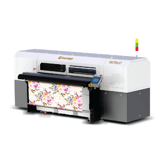
The Front View of the machine is shown as below: Fig 1: Displaying the Front View Table 1: Different Parts of the Printer 1. Light Tower 2. HMI Control Panel 3. Take Up Regulator 4. Water Tank 5. USB Socket VastraJet Page | 5... - Page 7 Fig 2: Displaying the Main Parts of the Machine (Front Side) Table 2: Different Parts of the Printer 1. Print Head Carriage 2. Negative Pressure Adjustment Valve 3. Head Cleaning Station 4. Switch Panel 5. Fabric Take Up System VastraJet Page | 6...
-
Page 8: Back View
Table 3: Different Parts of the Printer 1. Light Tower 2. Door Handle 3. Belt Tension Adjustment Screw 4. Main Power Switch 5. Power Cable Socket 6. Press Roller Lever 7. Fabric tensioner 8. Fabric Supply Rod 9. Wheels VastraJet Page | 7... - Page 9 Fig 4: Displaying the Main Parts of the Machine (Back Side) Table 4: Different Parts of the Printer 1. Main Ink Tank (Right Side) 2. Main Ink Tank (Left Side) 3. Water Tank 4. Water Inlet 5. Water Outlet 6. Filter Plate VastraJet Page | 8...
-
Page 10: Getting Familiar With Printer Manager Interface
Print Area, DPI, Pass, and more. • Job Preview: Show the job preview as well as print progress in this area. • Job List: Displays the thumbnail preview of added jobs. • Error message: Displays the system generated error messages. VastraJet Page | 9... -
Page 11: Getting Ready For Printing
Step 2: Turn ON the Main Power switch located on the back side of the machine, as shown below: Fig 7: Turning ON the Main Power Knob Step 3: Refill water tank with the clean water. Step 4: Run the wash cycle for 10 – 15 minutes. VastraJet Page | 10... - Page 12 Step 9: Check Carriage position and move it toward right, if required. The Carriage should be in the right side of the Home Position Limit Switch, as shown below: Fig 9: Checking the Carriage Position Step 10: Turn ON the Print Engine power, as shown below: Fig 10: Turn ON the Print Engine VastraJet Page | 11...
- Page 13 Step 17: Check whether Jetting and Brush Roller working properly or not. Step 18: Rip the image file using the Ripping software provided with the machine. Step 19: Set the print origin to specify the printing starting position. Now, the printer is ready for printing. VastraJet Page | 12...
-
Page 14: Signal Lamp Description
System Error Need to Restart Orange Printer is Working Printer in working mode Green Printer is ON Blue Printer is ON The Signal Lamp is shown in the image below: Fig 13: Displaying the Signal Lamp VastraJet Page | 13... -
Page 15: Setting Menu
The Setting window with the Printer tab is shown in the below image: Fig 14: Displaying the Setting Window Note: Spray Period value must be 10,000. Manual Spray settings are given as below: • Frequency : 10,000 • Period : 1000 VastraJet Page | 14... - Page 16 Fig 16: Displaying the Preference Tab Note: Unit value can be changed using the Unit drop down list. The Calibration tab is shown in the image below: Fig 17: Displaying the Calibration Wizard Note: Approximate Base Step value should be 14600. VastraJet Page | 15...
-
Page 17: Loading The Fabric
Fig 18: Inserting the Fabric Roll into to Supply Core Step 4: Remove the roller stopper pin and place the supply roller into the rear of the machine, as shown in the image below: Fig 19: Placing thee Supply Roller into the Rear VastraJet Page | 16... - Page 18 Step 6: Carefully stretch the fabric stretched to keep it wrinkle free and easily pass below the press roller. Additionally, pull down the press roller through toggle handle, as shown below: Fig 21: Stretching the Fabric VastraJet Page | 17...
- Page 19 Step 12: Set the take up power to 70% approx. (depends on the fabric type) and switch on the Take Up from the HMI. Additionally, move the belt forward a little, so that fabric gets securely winded into the take up roller. Now, the fabric gets loaded into the machine. VastraJet Page | 18...
-
Page 20: Filling Ink
The Main Ink Tanks are located at the back of the printer (four on each side) • Ink in the Main tanks is pumped to the Sub Ink Tanks located at the Carriage Assembly. The Ink Pumps are shown in the image below: Fig 25: Displaying the Ink Pumps VastraJet Page | 19... -
Page 21: Feeding Password
Password. Let’s learn to feed password in the machine. Follow these steps to change the passwords of the printer: Step 1: Click on the Main Menu→Tools→Password path, as shown below: Fig 27: Selecting the Password Option VastraJet Page | 20... - Page 22 Step 4: Click on the Exit button to close the Password window (Refer to Fig 29). Note: When “First Warning” appears, kindly contact Head Office with the following screen: • Password Screen (Refer to Fig 28) • About Us Screen Fig 29: Displaying the About Us Screen VastraJet Page | 21...
-
Page 23: Glue Coating
Note: Average consumption for the Cleantek solvent is 500ml for one time. Approximate consumption of chemicals for a year: • Prima : Approx. 2 Ltrs • Therma: Approx. 2 Ltrs • Perma: Approx. 5 Ltrs • Cleantek: Approx. 4 Ltrs VastraJet Page | 22... - Page 24 Aliphatic • Hexane • Cyclohexane • Ketone • Acetone • Methyl ethyl ketone (MEK) • Chlorinated hydrocarbon • Methyl chloride • (Mono)chlorbenzene • Chloroform • Trichloroethane • Trichloroethylene • Ether • Ethyl ether • Tetrahydrofurane (THF) VastraJet Page | 23...
-
Page 25: Glue Process Preparation
Step 3: Run the Wash Cycle from HMI, simultaneously belt can be cleaned by wiping with cloth. Fig 31: Running the Wash Cycle Step 4: Put masking PVC tape on both edges of the Conveyor Belt, by simultaneously moving the belt through HMI in slow speed. Fig 32: Using Masking Tape VastraJet Page | 24... -
Page 26: Glue Coating Procedure
3 persons will be required for this process. Follow these steps to start the glue coating process: Step 1: Put the Press Roller down. Fig 34: Closing the Press Roller VastraJet Page | 25... - Page 27 Fig 35: Enabling the Glue Cycle Mode Step 3: Go to the back of the machine. Pour the 70% glue equally throughout the belt, near the Press Roller, leaving the 10cm from both the edges. Fig 36: Pouring the Glue VastraJet Page | 26...
- Page 28 Fig 38: Spreading the Glue Step 6: Wherever the glue under the press roller is diminishing, pour the remaining glue over such areas. VastraJet Page | 27...
- Page 29 Slightly rotate the Press Roller in opposite direction, to move the sticky portion upwards away from the belt. • Lift the Press Roller from the both sides at a time and stop the glue cycle immediately from the HMI screen. Fig 40: Lifting Up the Press Roller VastraJet Page | 28...
-
Page 30: Glue Removing Preparation
Note: Do not use the Belt Washing Unit during the glue coating or glue removing process. Additionally, glue or the cleaner may damage the brush-roller or sponge roller, thus put a cover on the washing unit. VastraJet Page | 29... - Page 31 Fig 42: Wiping the Belt Step 3: Pour cleaner liquid (Solvtek) onto wipe clothes. Fig 43: Pouring Cleaner Liquid Step 4: Wait 5 minutes to dissolve glue. Step 5: Wipe dissolved glue and cleaner by wipe clothes. VastraJet Page | 30...
- Page 32 Step 9: After clean up the part, turn belt and repeat cleaning until clean up over all. Remove cover sheet which covers washing unit. Step 10: Finally, remove remained cover sheets, and keep the belt dry. Fig 46: Removing the Cover Sheet VastraJet Page | 31...
-
Page 33: Control Panel Operational Flow Chart
Make Ready IR Dryer Fan Advance Belt Speed Glue Cycle Reverse Belt Speed Tub Down Cycle Time Tub Down Tub Down Stop Glue Process Brush OFF Belt Direction Take Up CW Heater Take Up CCW Continue Continue VastraJet Page | 32... - Page 34 Process Value Wash Settings At Tuning Belt Dryer OFF Heat PID & Hysteresis IR Dryer OFF Set Value Spreader OFF Temp. Unit Centigrade Brushing OFF Washing OFF Back Heater Sensor Type Control Method Heat Alarm Settings VastraJet Page | 33...
-
Page 35: Control Panel Operations
After unlocking the Start Up screen, the NO CYCLE IS SELECTED (also known as Main Menu) screen appears with OPERATIONS and PRINT TO PREPARE options, as shown below: Fig 48: Displaying the NO CYCLE IS SELECTED Screen VastraJet Page | 34... -
Page 36: Mode Settings
PREPARE TO PRINT: Move to the PREPARE TO PRINT screen to make the Conveyor Belt system “Online”. Mode Settings In VastraJet, there are two modes viz. OPERATIONS and PREPARE TO PRINT. Let’s discuss them one by one. OPERATIONS Mode When you select the OPERATIONS icon on the HMI, the OPERATIONS screen appears as shown below:... -
Page 37: Service Mode
Controlling Belt Motion To control the belt motion, select the BELT icon from the SERVICE MODE screen (Refer to Fig 32). The BELT MOTION screen appears as shown below: Fig 51: Displaying the BELT MOTION Screen VastraJet Page | 36... -
Page 38: Setting Belt Speed
Now, enter the belt speed in the Numeric Keypad and select the Enter button to set the belt speed. Setting Washing Unit To set the position of washing tub, select the TUB icon from the SERVICE MODE screen. The WASHING UNIT screen appears, as shown below: Fig 53: Displaying the WASHING UNIT Screen VastraJet Page | 37... -
Page 39: Controlling Take Up Motion
Fig 54: Displaying the TAKE UP MOTION Screen Using the TAKE UP MOTION screen, you can perform the following actions: • TAKEUP CW: Move the take up in clockwise direction. • TAKEUP CCW: Move the take up in anti-clockwise direction. VastraJet Page | 38... -
Page 40: Setting Glue Cycle
Setting Wash Cycle To start the wash cycle, select the WASHING CYCLE option from the OPERATIONS screen (Refer to Fig 32). The WASHING CYCLE screen appears as shown below: Fig 56: Displaying the WASHING CYCLE Screen VastraJet Page | 39... -
Page 41: Controlling Heaters Settings
To change or update the heater settings, select the HEATERS button from the WASH CYCLE SETTINGS screen (Refer to Fig 40). The HEATERS SETTINGS screen appears as shown below: Fig 58: Displaying the HEATERS SETTINGS Screen VastraJet Page | 40... -
Page 42: Prepare To Print Option
After making the desirable changes, select the MAKE READY option to save the selection and the Confirmation screen appears to ask whether you want to save the changes or not, as shown below: Fig 60: Displaying the Confirmation Dialog Screen VastraJet Page | 41... - Page 43 • HEATERS: Heater temperature can be set using the HEATERS icon. • OVERRIDE: Heaters can be overridden to go “ONLINE” • TAKEUP POWER: Display the take-up power on the screen. VastraJet Page | 42...
-
Page 44: Printer Software Operations
Fig 64: Displaying the Origin Value Now, the printing origin gets set. Additionally, you can also enter the print origin value manually in the Origin X field under the Print Parameter section. VastraJet Page | 43... -
Page 45: Calibrating Wizard
Print Heads should be calibrated to ensure good printing quality. To open the Calibration Wizard, click on the Main Menu→Tools→Calibration Wizard path, as shown below: Fig 65: Selecting the Calibration Wizard Option This should bring up the calibration wizard which is shown below: Fig 66: Displaying the Calibration Wizard VastraJet Page | 44... -
Page 46: Horizontal Calibration
Right to Left test print at“0” position. In case of error in the Bi-Direction offset, the Left to Right and Right to Left print would align at some other point on the scale. VastraJet Page | 45... - Page 47 “0” position, but at some other point on the calibration scale. The position at which the test head aligns perfectly with the reference head, indicates the error in position. VastraJet Page | 46...
- Page 48 The Left Calibration Result is shown in the image below: Fig 69: The Horizontal Left Check VastraJet Page | 47...
-
Page 49: Step Calibration
Step size needs to be adjusted for multiple factors like thickness and roughness of the print media etc. Step calibration should be used to fine adjust the step size and has to be done for each desired pass. VastraJet Page | 48... - Page 50 Step 3: Click on the => icon (Refer to Fig 55) on the Step Calibration window. The correction value result will be reflected in the Step field (Refer to Fig 55). The same step value will also be displayed in the Steps field on the Quick Access Toolbar. VastraJet Page | 49...
-
Page 51: Setting Print Parameters
Fig 74: Clicking on the Add Job Button The Open window appears on the screen. Step 2: Navigate to the location where the image file with extension “.prt” and “.prn” is stored (Refer to Fig 58). VastraJet Page | 50... - Page 52 Step 3: Click on the Open button to add the file into the Job List area, as shown below: Fig 75: Adding the Job Now, the selected image appears in the Job List area, as shown below: Fig 76: Displaying the Added Job and Their Details VastraJet Page | 51...
-
Page 53: Editing Job
Step 4: Select the desired checkbox in front of the Clip, Reverse Print, and Tile options. On clicking to any option, its related parameters get appeared on the right pane and you can edit them as per the requirements. In our case, we have selected the Clip checkbox. VastraJet Page | 52... -
Page 54: Ripping And Printing
Modes Print Passes Print DPI (512) Print Passes Print DPI (1024) Mode 1 360X360 2 and 4 540X720 Mode 2 3 and 6 360X540 3 and 6 540X1080 Mode 3 360X720 540X1440 VastraJet Page | 53... - Page 55 ‘Use file setting’ has be enabled from the Printer Manager software. After issuing the Print command, the printing gets started and its progress details displays in the Job Information area, as shown below: Fig 82: Displaying the Printing Details VastraJet Page | 54...
-
Page 56: Pausing And Canceling Printing
Fig 83: Issuing the Pause or resume Command Similarly, you can abort the process by right clicking on the selected Job in the Job List area and select the Abort Job option from the context menu. VastraJet Page | 55... -
Page 57: Head Cleaning
Head Blotting In Head Blotting, extra ink below the Heads is to be soaked using the Head Sponge Roller, as shown below: Fig 85: Displaying the Head Sponge Roller VastraJet Page | 56... -
Page 58: Head Spraying
When heads are sprayed all the nozzles are actuated at a high rate which helps in opening up dry nozzles of the printer. To perform head spraying, click on the Spray button available under the Quick Access Toolbar, as shown below: Fig 86: Displaying the Spray Button VastraJet Page | 57... -
Page 59: Switch Off Procedure
Fig 87: Lifting Up the Press Roller Step 4: Put the HMI in Offline mode and run the wash cycle for 10 minutes. Step 5: Move the washing tub down using the HMI, as shown below: Fig 88: Moving the Washing Tub VastraJet Page | 58... - Page 60 Step 9: Move the Capping Knob to engage the Capping Station, as shown below: Fig 90: Removing the Capping Knob Step 10: Switch OFF the print engine, as shown below: Fig 91: Switch OFF the Print Engine VastraJet Page | 59...
- Page 61 Step 11: Check the belt position with respect to the roller. In case, Belt is not in “Center”, then move the Belt in the reverse direction using the Glue Cycle window till the Belt comes in center. Step 12: Turn OFF the main power. Step 13: Close all the covers of the printer. VastraJet Page | 60...
-
Page 62: Do's And Don't
7. Never keep the printing continue, if the belt has shifted more 8. Don’t pull the tub without disconnecting the brush motor connector during tub maintenance 9. Don’t run the belt without jetting ON 10. Don’t run the jetting pump when water tank is empty VastraJet Page | 61... - Page 63 13. Don’t move the carriage over the Capping Station when printer is OFF and capping is in UP position 14. Don’t turn the Capping Knob during printing 15. Don’t print when glue layer is not smooth/peeled OFF VastraJet Page | 62...
-
Page 64: Maintenance
Wait for the completion of the current printing process. If the print command repeats, then immediately stop giving the next print command for printing. b) Takeout the fabric, lower down the tub, and run glue cycle in reverse direction with the 70% speed. VastraJet Page | 63... -
Page 65: Belt Shifting Control
In the old version, the Slider Block screw has to be loosen. To control belt shifting, holding the Adjust Roller and slightly pull or push the sliding block as per requirement. After the required alignment is achieved, tighten all the screws. Please note: Belt tensioner screw has not be disturbed in normal cases. VastraJet Page | 64... - Page 66 Case 1: Belt shifting Away from the Carriage Home Position VastraJet Page | 65...
-
Page 67: Glue Coating Layer
Maintain the head negative air pressure between -2.7 to -3.2. If the negative pressure is slightly be high or low, adjust it using the regulator knob. The Negative Air Pressure display switch and regulator are shown in the image below: Fig 93: Adjusting the Head Negative Air Pressure VastraJet Page | 66... -
Page 68: Daily Maintenance
Don’t turn ON the Capping knob when printer is running • Keep the Humidifier knob in minimum position • Always pour distill water in the Capping tray to avoid germs • Replace the head cleaning roller, if surface wear out. VastraJet Page | 67... -
Page 69: Weekly Maintenance
• Open the drain valve of the Main tank inlet to empty it. • Remove the tub front covers. • Lower down the tub using the HMI screen, as shown below: Fig 95: Removing the Tub VastraJet Page | 68... - Page 70 Fig 97: Removing the Trolley Note: Care has to be taken, not to damage the wheels while moving the trolley outside. • After completing the cleaning, reversely follow the above given steps to fix the tub. VastraJet Page | 69...
-
Page 71: Monthly Maintenance
Monthly Maintenance • LM guide should be wiped monthly. • Cleaning the floor particularly the area near the water tank and washing tub. • Encoder strip should be cleaned gently with wet tissue paper, on weekly basis. VastraJet Page | 70... -
Page 72: Troubleshooting
Ink overflowed from sub tank and filled in the reservoir • Vacuum is not generated by pump (pump failure) • Any ink/air tube is having leakage/cut/loose on fitting joints • Vacuum pump connector is loose/open from MMCB VastraJet Page | 71... -
Page 73: Fabric Not Sticking To Belt
USB cable is loose / faulty • Image files are heavy in size • Ground wire is disconnected • Encoder scale is having ink stains/scratches • Pulley or belt is slipping • Ripped file is having error VastraJet Page | 72... -
Page 74: Print Is Shifting Wrt Fabric/ Junk Printing
Incorrect resolution is selected • X div is selected "High Speed" instead of "High Precision" Lines in Prints • Nozzle blocked in heads (check nozzle test) • Incorrect feed step (calibration required) • Belt motor coupling loose VastraJet Page | 73... -
Page 75: Error Handling
Kindly refer to the error code 40030000 USB communication error 4002001A. PRT resolution mismatch with printer Incorrect Print Mode is selected. 40030009 resolution! VastraJet Page | 74... - Page 77 For Any Query Please Contact Us www.colorjetgroup.com Call us on +91-120-4548195 Email on info@colorjetgroup.com For Ink Enquiry:- sales@colorjetgroup.com For Support:- support@colorjetgroup.com...
Need help?
Do you have a question about the Vastrajet and is the answer not in the manual?
Questions and answers