Table of Contents
Advertisement
Quick Links
Advertisement
Table of Contents

Related Manuals for Colorjet TXF


Summary of Contents for Colorjet TXF
- Page 1 India’s largest manufacturer of digital inkjet printers U S E R M A N U A L...
- Page 3 This manual serves as the reference tool which guides their customers how to use or operate the TXF machine without anyone else assistance. The information provided in this document ensures its uniqueness and language quality.
-
Page 4: Table Of Contents
Table of Contents 1. About Document ............................5 Purpose ................................5 Intended Audience ............................5 2. Printer Overview ............................6 3. Control Panel (Print Engine) ........................... 8 Main Menu ..............................9 Language Menu ............................10 Cleaning Menu ............................. 10 4. Control Panel (Conveyor Belt) ........................11 Start Up Screen ............................ - Page 5 Glue Removing Procedure ........................29 Fabric Loading .............................. 31 6. Printing ................................ 34 Check Ink Level ............................34 Head Height Adjustment..........................34 Performing Normal Cleaning........................36 Setting Print Origin............................37 Performing Test Print ........................... 39 Printer Calibration............................40 Feed Calibration ............................40 Bidirectional Calibration...........................
- Page 6 Monthly Maintenance ..........................63 9. Troubleshooting ............................64 Page | 4...
-
Page 7: About Document
1. About Document Purpose The purpose of this document is to guide and educate the targeted audience about the Printer and it’s related functionality so that they can easily and effectively handle it as per their requirements. Additionally, this document also provides step-wise instructions for handling and operating the various aspects of the printer and its related software with the help of graphical screens for easy and better understanding. -
Page 8: Printer Overview
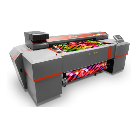
2. Printer Overview The Front View of the printer is shown in the image below: Fig 1: Displaying the Front View of the Printer Table 1: List of Different Parts of the Printer 1. Leveler 2. Left Supply Cabinet (Front) 3. - Page 9 The Back View of the printer is shown in the image below: Fig 2: Displaying the Back View of the Printer Table 2: List of Different Parts of the Printer 1. Left Emergency Button 2. Right Emergency Button 3. Left Belt Tensioner Bolt 4.
-
Page 10: Control Panel (Print Engine)
3. Control Panel (Print Engine) The Control Panel is shown in the image below: Fig 3: Displaying the Control Panel Layout The description of each control button is given as below: POWER ON/OFF: Get ON or OFF the printer. ... -
Page 11: Main Menu
Main Menu The Main Menu and its related sub options are shown in the image below: Menu Media Settings Load Preset Save Auto Display Test Print Adjust BI-DIR. Simple Setting H1 & H2 Detail Setting Test Print Calibration Settings Media Alignment Media Alignment Test Print High... -
Page 12: Language Menu
Language Menu The Language Menu and its related options are shown in the image below: Menu English Language Length Unit Temp. Unit Cleaning Menu The Cleaning Menu and its related options are shown in the image below: Menu Normal Cleaning Cleaning Medium Cleaning Powerful Cleaning... -
Page 13: Control Panel (Conveyor Belt)
4. Control Panel (Conveyor Belt) Start Up Screen Switch ON the printer from the main power panel, the following Start Up screen appears on HMI, as shown below: Fig 4: Displaying the Start Up Screen Tapping the Start Up screen to go to the next screen, as shown below: Fig 5: Displaying the “NO CYCLE IS SELECTED”... -
Page 14: Operations
The description of different options in the NO CYCLE IS SELECTED screen is given as follow: OPERATIONS: Move to the OPERATIONS screen and perform different operations viz. DIAGNOSTICS, GLUE CYCLE, and WASH CYCLE. PREPARE TO PRINT: Move to the PREPARE TO PRINT screen to make the Conveyor Belt system “Online”. -
Page 15: Service Mode
Service Mode To open the SERVICE MODE screen, select the DIAGONSTICS icon from the OPERATIONS screen (Refer to Fig 6). The SERVICE MODE screen is shown as below: Fig 7: Displaying the SERVICE MODE Screen The description of different options in the SERVICE MODE screen is given as follow: ... -
Page 16: Controlling Belt Motion
Controlling Belt Motion To control the belt motion, select the BELT icon from the SERVICE MODE screen (Refer to Fig 7). The BELT MOTION screen appears as shown below: Fig 8: Displaying the BELT MOTION Screen Using the BELT MOTION screen, you can perform the following actions: ... -
Page 17: Setting Washing Unit
Setting Washing Unit To set the position of washing tub, select the TUB icon from the SERVICE MODE screen. The WASHING UNIT screen appears, as shown below: Fig 10: Displaying the WASHING UNIT Screen Using the WASHING TUB screen, you can perform the following actions: ... -
Page 18: Setting Glue Cycle
Using the TAKE UP MOTION screen, you can perform the following actions: TAKEUP CW: Move the take up in clockwise direction. TAKEUP CCW: Move the take up in anti-clockwise direction. Setting Glue Cycle To start the glue cycle, select the GLUE CYCLE option from the OPERATIONS screen (Refer to Fig 6). The GLUE CYCLE screen appears as shown below: Fig 12: Displaying the GLUE CYCLE Screen Using the GLUE CYCLE screen, you can perform the following actions:... -
Page 19: Setting Wash Cycle
Setting Wash Cycle To start the wash cycle, select the WASHING CYCLE option from the OPERATIONS screen (Refer to Fig 6). The WASHING CYCLE screen appears as shown below: Fig 13: Displaying the WASHING CYCLE Screen Using the WASHING CYCLE screen, you can perform the following actions: ... -
Page 20: Controlling Heaters Settings
Controlling Heaters Settings To change or update the heater settings, select the HEATERS button from the WASH CYCLE SETTINGS screen (Refer to Fig 14). The HEATERS SETTINGS screen appears as shown below: Fig 15: Displaying the HEATERS SETTINGS Screen Using the above screen, change the belt and print dryers settings by updating the SET and PRESET TEMPERATURES. - Page 21 After making the desirable changes, select the MAKE READY option to save the selection and the Confirmation screen appears to ask whether you want to save the changes or not, as shown below: Fig 17: Displaying the Confirmation Dialog Screen On clicking to the YES button, the ONLINE screen appears as shown as shown below: Fig 18: Displaying the ONLINE Screen Using the above screen, you can make the Conveyor System Online or Offline.
-
Page 22: Before Use
5. Before Use Preparation Before Starting the Printer Before start using the printer, please check and confirm the below mentioned instructions for effective and efficient utilization of the machine: Check the room temperature and maintain it Check the ink level of each color in the ink tank ... - Page 23 The Start Up Screen of HMI appears as shown below: Fig 20: Displaying the Start Up Screen Step 2: Remove the fabric, if any. Step 3: Check whether the belt is in the Centre or not. If not, Centre it by moving the belt in the reverse direction and adjust the shifting control shaft.
-
Page 24: Glue Implementation
Step 10: Set the starting position of the print from the Control Panel of the print engine. Step 11: Issue the test print using the TEST PRINT button from the Control Panel of the print engine. Step 12: Start printing. Step 13: Care about fabric handling from Supply and Take Up sides (particularly till time the fabric is wind up in take up roller). -
Page 25: Stages Of Glue (Adhesive) Process
Stages of Glue (Adhesive) Process Stage 1: Prima coat Stage 2: Therma coat Stage 3: Perma coat An interval of 4hrs is required for the glue to set and dry. After each glue coat, run the glue cycle for 50 minutes with glue heater ON. - Page 26 Step 3: Run the Wash Cycle from HMI, simultaneously belt can be cleaned by wiping with cloth. Fig 24: Running the Wash Cycle Step 4: Put masking PVC tape on both edges of the Conveyor Belt, by simultaneously moving the belt through HMI in slow speed.
-
Page 27: Glue Coating Procedure
Step 6: Keep ready following items:- Glue container(500-600ml), whichever required Home cleaner liquid spray Pouring container Waste bin Woven cotton bud sticks (for spreading the glue) Glue Coating Procedure Note: Extreme care to be taken during the glue process, any negligence may render the coat unsuitable for use, and complete process may be required to be repeated. - Page 28 Step 3: Go to the back of the machine. Pour the 70% glue equally throughout the belt, near the Press Roller, leaving the 10cm from both the edges. Fig 29: Pouring the Glue Step 4: Let the two persons hold the Press Roller firmly, so that it doesn’t move. Fig 30: Closing the Press Roller Page | 26...
- Page 29 Step 5: Once the glue has crossed the press roller, speed can be increased to 20. Using the cotton bud stick, keep spreading the glue from the area where glue is in excess, to the area wherever the glue is less in quantity. Fig 31: Spreading the Glue Step 6: Wherever the glue under the press roller is diminishing, pour the remaining glue over such areas.
- Page 30 Step 9: Once the glue seems to be deactivated, stop spraying liquid, and do simultaneously and quickly below steps:- Slightly rotate the Press Roller in opposite direction, to move the sticky portion upwards away from the belt. Lift the Press Roller from the both sides at a time and stop the glue cycle immediately from the HMI screen.
-
Page 31: Glue Removing Preparation
Step 13: Leave machine idle for 4 hours to let glue dry and set. (Next glue coat has to be done only after resting period of 4 hours) Above process has to be repeated for every glue coat process. Glue Removing Preparation Prepare and ready the following below mention things before removing glue: ... - Page 32 Step 4: Wait 5 minutes to dissolve glue. Step 5: Wipe dissolved glue and cleaner by wipe clothes. Step 6: After wiping out the part, turn the belt and repeat wiping until wipe out over all. Fig 37: Wiping the Glue Step 7: Spray or pour purified water onto the belt.
-
Page 33: Fabric Loading
Fabric Loading Follow these steps to load fabric in the printer: Step 1: Keep the well pressed and pre-treated fabric roll winded into the empty core of diameter 65-70mm. Insert the supply roller into the core of the fabric roll. Attach the core holders on both ends and tighten them. Fig 40: Displaying the Fabric Roll Step 2: Remove the roller stopper pin, and place the supply roller into the rear of the machine. - Page 34 Step 3: Fix the takeup roller by following the given instructions: a. Using the Takeup option in the service mode, rotate and align the Takeup Motor Coupling so that takeup roller can easily fix in it, as shown below: Fig 42: Fixing the Core Holder into Takeup Roller b.
- Page 35 Step 5: Adjust the Fabric Tensioner (as shown in Fig 45) such that the fabric get stretched and to remove any slack. Do not over tension the fabric. Fig 45: Adjusting the Fabric Tensioner Step 6: Press Belt Forward from HMI to feed fabric forward (Care to smooth out the wrinkles, if any). Pass the fabric between the front Print Dryer and the Stretcher Rollers.
-
Page 36: Printing
6. Printing Check Ink Level Check the ink level in cartridges and refill it, if required, as shown below: Fig 48: Displaying the Main Ink Tank Head Height Adjustment Follow these steps to adjust the head height as per the requirements of the fabric thickness: Step 1: Press the MENU button from the Control Panel of the print engine. - Page 37 Step 6: Press the ENTER button to select the CHANGE option to modify the settings, as shown below: Fig 51: Setting the Head Height Step 7: After selecting the CHANGE option, open the front cover to adjust the head height. Step 8: Move the Height Adjustment Lever to adjust Print Head height viz.
-
Page 38: Performing Normal Cleaning
Performing Normal Cleaning Follow these steps to perform normal cleaning: Step 1: Press the CLEANING button from the Control Panel of the print engine, as shown below: Fig 53: Clicking the Cleaning Button Additionally, select the MENUCLEANING path and you are redirected to the CLEANING menu. The CLEANING screen with its related options appears. -
Page 39: Setting Print Origin
Setting Print Origin Follow these steps to set the print origin; Step 1: Move the carriage using the Left, Right, Up, or Down arrow button from the Control Panel of the print engine, at the location from where you want to start the printing. Step 2: After setting the location, press the BASE POINT button from the Control Panel, as shown below: Fig 56: Pressing the BASE POINT Button When the process is completed, the following screen with character “B”... - Page 40 Step 3: Press the Right arrow button and select the TEST PRINT POS option, as shown below: Fig 59: Selecting the TEST PRINT POS Option On selecting the TEST PRINT POS option, the following screen appears, as shown below: Fig 60: Displaying the TEST PRINT POS Sub Options Step 4: Select the desired option either FEED or SCAN and press the ENTER button (Fig.
-
Page 41: Performing Test Print
Performing Test Print Follow these steps to perform test print: Step 1: Set the print origin by following all the steps mentioned in the “Setting Print Origin” section. Step 2: Press the TEST PRINT button from the Control Panel of the print engine and hold it for few seconds. The following test print is printed on the fabric, as shown below: Fig 61: Showing the TEST PRINT Result In the above figure, you can see that few nozzles are not firing. -
Page 42: Printer Calibration
Printer Calibration Feed Calibration The Feed Calibration is used for the printer step calibration to verify and correct the fabric feeding. The printer prints a complete image in several passes. A pass is the horizontal carriage sweep perpendicular to the fabric movement. - Page 43 The CALIBRATION screen with TEST PRINT option appears, as shown below: Fig 64: Issuing the Test Printing Step 4: Press the ENTER button from the Control Panel of the print engine for test printing (Refer to Fig 64). Step 5: After finishing the test printing, press the Down arrow button to select the SETTING option, as shown below: Fig 65: Selecting the SETTING Option Step 6: Press the Right arrow button to confirm the selection.
-
Page 44: Bidirectional Calibration
Bidirectional Calibration Bi-directional calibration is performed to achieve printing accuracy between the “Left to Right” and “Right to Left” print sweeps. If the bi-direction offset value is correct, the Left to Right test print would align accurately with the Right to Left test print at “0” position. In case of error in the BI-DIR offset, the Left to Right and Right to Left print would align at some other point on the scale. - Page 45 Step 4: After finishing the test printing, press the Up or Down arrow buttons and select the SIMPLE SETTING option to enter the correction value, as shown below: Fig 70: Selecting the SIMPLE SETTING Option Step 5: Press the Right arrow button to select the SIMPLE SETTING option (Refer to Fig 70). The SIMPLE SETTING screen appears.
-
Page 46: Issuing Printing Command
Issuing Printing Command With TXF, a rip software is provided. Using this ripping software, import the selected image and issue the Print command. Before printing, make sure the following instructions should be maintained: Make Conveyor Belt Online Set the Base Point Pausing or Canceling Print At any instance of time, user can pause or cancel the printing during it process. -
Page 47: Switch Off Procedure
Switch OFF Procedure Follow these steps to switch off the printer: Step 1: Take a test print to verify the result is same as when the printer is ON. If there is a difference then perform the remedial actions. Step 2: Lift up the Press Roller. Step 3: Remove the fabric from the belt. - Page 48 Step 9: Turn OFF the power switch available on the back side of the printer to stop the Conveyor Belt, as shown below: Fig 76: Turning ON the Power Switch Step 10: Cover the printer to protect the belt and other parts from dust. Note: Don’t Switch OFF the printer from the main power of print engine, as an automatic maintenance function is running which protects the Print Head nozzles from getting dried.
-
Page 49: Utilizing The Preset Function
7. Utilizing the Preset Function The PRESET function enables users to save and load the previously made printer settings. Saving Preset Settings Follow these steps to save the printer settings: Step 1: Press the MENU button from the Control Panel of the print engine. Step 2: Press the Down arrow button and select the PRESET option, as shown below: Fig 77: Selecting the PRESET Option Step 3: After selecting the PRESET option, press the Right arrow to confirm the selection and select the SAVE... -
Page 50: Loading The Previously Saved Settings
Loading the Previously Saved Settings Follow these steps to load the previously saved preset: Step 1: Press the MENU button from the Control Panel of the print engine. Step 2: Press the Down arrow button and select the PRESET option, as shown below: Fig 81: Selecting the PRESET Option Step 3: After selecting the PRESET option, press the Right arrow and select the Load option, as shown below: Fig 82: Selecting the LOAD Option... -
Page 51: Automatically Loading The Saved Preset When Fabric Is Loaded
Automatically Loading the Saved Preset When Fabric is Loaded Follow these steps to automatically load the previously saved preset: Step 1: Press the MENU button from the Control Panel of the print engine. Step 2: Press the Down arrow button and select the PRESET option, as shown below: Fig 84: Selecting the PRESET Option Step 3: After selecting the PRESET option, press the Right arrow and select the AUTO DISPLAY option, as shown below:... -
Page 52: Enabling The Sleep Mode
8. Enabling the Sleep Mode This machine embeds with the power saving feature, which is best known as “Sleep Mode”. The Sleep mode is activated when the machine is idle or not used for 30 or more minutes. In this mode, the sub power switch flashes which means that the machine is virtually ON but not in use. -
Page 53: Maintenance
9. Maintenance Print Engine Maintenance Print Head Print Head is an important and delicate part of the printer. Thus, it must be handled with care to ensure the long life of the print heads. For print head maintenance, the following instructions should be taken care: ... - Page 54 Step 2: Press the MENU button from the Control Panel of the print engine. Step 3: Press the Up or Down arrow button and select the CLEANING option. Step 4: Again, Press the Up or Down arrow button and select the MEDIUM CL. option, as shown below: Fig 92: Selecting the MEDIUM CL.
-
Page 55: Powerful Cleaning (Not Recommended)
Powerful Cleaning (Not Recommended) Follow these steps to perform the powerful cleaning: Step 1: Follow Step 1 – Step 3 of the Medium Cleaning section. Step 2: Press the Up or Down arrow button and select the POWERFUL CL. option, as shown below: Fig 95: Selecting the POWERFUL CL. - Page 56 Enabling the Manual Cleaning Mode Follow these steps to set the manual cleaning mode: Step 1: Remove the previously loaded fabric. Step 2: Press the MENU button from the Control Panel of the print engine. Step 3: Press the Up or Down arrow button and select the SUB MENU option, as shown below: Fig 97: Selecting the Sub Menu Option Step 4: Press the Right arrow button and select the MAINTENANCE option from the list, as shown below: Fig 98: Selecting the Maintenance Option...
- Page 57 Cleaning Wipers Follow these steps to clean wipers: Step 1: Set the Manual Cleaning mode by performing all the steps mentioned in the “Setting Manual Cleaning Mode” section. On selecting the CLEANING option, two sub-options appear on the screen viz. OPEN COVER R and OPEN COVER L.
- Page 58 Step 4: Clean both wipers one by one with the help of wet cleaning stick, as shown below: Fig 105: Cleaning the Wiper Step 5: After completing the wiper cleaning, press the ENTER button from the Control Panel of the print engine.
- Page 59 Cleaning the Surrounding Area of Print Head Follow these steps to clean the surrounding area of Print Head: Step 1: Set the Manual Cleaning mode by performing all the steps mentioned in the Setting Manual Cleaning Mode section. Step 2: Press the Up or Down arrow and select the OPEN COVER L option. Step 3: Press the ENTER button from the Control Panel of the print engine.
- Page 60 Step 9: Start the cleaning the area near to the Print Head, as shown below: Left Side Right Side Fig 111: Cleaning the Capping Station and Surrounding of Print Head Note: While cleaning the Print Head, don’t touch the surface of Print Head. Step 10: After cleaning, press the ENTER button from the Control panel.
-
Page 61: Conveyor Belt Maintenance
Conveyor Belt Maintenance Belt Maintenance Note: Conveyor Belt is an important part of the printer and has to be handled carefully. During printing, the belt position has to be monitored from time to time, belt should always be running well inside the rollers. Centering of Belt Below section explains about centering of belt, when it has shifted towards edge of the roller: ... - Page 62 Case-I: Belt Shifted Towards Left Case-2: Belt Shifted Towards Right Page | 60...
-
Page 63: Glue Coating Layer
Glue coating layer It is strictly recommended that company suggested glue has to be used, else it may cause damage to sponge rollers, Conveyor Belt, brush motor assembly and belt motor coupling Glue coating has to be checked from time to time for its adhesive strength. Whenever required, fresh coating is to be done. - Page 64 Precautions: Tub should always be lowered before turning off machine. Never run washing tub with jetting pump off. Never engage washing tub immediately after glue coating. Always use clean RO processed water for washing system, for longer life of related parts. ...
- Page 65 Water tank filter plates should be cleaned with hard brush to remove stuck threads. Tub bottom has to be rinsed and cleaned. Monthly Maintenance LM guide to be wiped off to remove dust particles on monthly basis. ...
- Page 66 9. Troubleshooting PRINTER NOT INITIALIZING Print engine is OFF Servo board not powered ON / Faulty Main Board faulty JETTING PUMP NOT WORKING Jetting pump float is down Water is less in tank Not enabled from HMI ...
- Page 67 PRINT NOT DRYING/INK MARKS ON BACK OF FABRIC Print dryer is not on or not working Dryer temperature is not sufficient Coating of fabric is not there/ correct Fabric supporting bar and Take up roller is stained with ink FABRIC STICK ON THE COVEYOR BELT NOT WINDING ON TO THE CORE ...
- Page 69 For Any Query Please Contact Us www.colorjetgroup.com Call us on +91-120-4548195 Email on info@colorjetgroup.com For Ink Enquiry:- sales@colorjetgroup.com For Support:- support@colorjetgroup.com...
Need help?
Do you have a question about the TXF and is the answer not in the manual?
Questions and answers