Colorjet VERVE User Manual
Hide thumbs
Also See for VERVE:
- Installation and troubleshoot manual (38 pages) ,
- User manual (40 pages)
Table of Contents
Advertisement
Quick Links
Advertisement
Table of Contents

Related Manuals for Colorjet VERVE


Summary of Contents for Colorjet VERVE
- Page 3 This manual serves as the reference tool which guides their customers how to use or operate the VERVE machine without anyone else assistance. The information provided in this document ensures its uniqueness and language quality.
-
Page 4: Table Of Contents
Editing Job ..............................30 Ripping and Printing ............................31 Pausing and Canceling Printing ........................31 Head Height Measurement ........................... 32 UV Setting ..............................33 Feeding Time and Language Passwords ......................34 8. Head Cleaning ............................... 35 VERVE Page | 2... - Page 5 Lines in Print ..............................40 Heaters Not Working ............................ 41 Head Not Firing ............................. 41 A Color Ink Not Supply ..........................41 UV Lamp Not Working ..........................41 UV Ink is not Fully Cured ..........................41 VERVE Page | 3...
-
Page 6: About Document
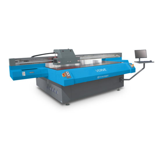
Thus, this document is designed to facilitate both types of users. 2. Machine Overview The Machine Overview is shown in the image below: Fig 1: Displaying the Machine Overview VERVE Page | 4... - Page 7 Left Switch: Control the frequency of the left UV Lamp’s light for drying prints viz. High, Low, and Medium. o Right Switch: Control the frequency of the right UV Lamp’s light for drying prints viz. High, Low, and Medium. • Emergency Stop Buttons: Use in emergency situations for stopping the printing process. VERVE Page | 5...
-
Page 8: Control Panels
3. Control Panels In VERVE, there are two control panels viz. Left and Right. Let’s discuss each control panel one by one in the upcoming section. Left Control Panel The Left Control Panel is used for controlling and managing Print Bed vacuum using the Pump 1 and Up Vacuum buttons. -
Page 9: Right Control Panel
Left Lamp Regulator: Control the frequency of the left UV Lamp’s light used for drying the print from left side. • Right Lamp Switch: Switch ON/OFF the Right UV Lamp. • Right Lamp Regulator: Control the frequency of the right UV Lamp’s light used for drying the print from right side. VERVE Page | 7... -
Page 10: Getting Familiar With Printer Manager Interface
Print Area, DPI, Pass, and more. • Job Preview: Show the job preview as well as print progress in this area. • Job List: Displays the thumbnail preview of added jobs. • Error message: Displays the system generated error messages. VERVE Page | 8... -
Page 11: Main Menu Options
Printer Manager software. • Edit: Using this option, you can edit the previously made settings of Printer. On clicking the Edit option, the Setting window with Printer, Move, Preference, and Calibration tabs appears on the screen. VERVE Page | 9... - Page 12 The Setting window with the Printer tab is shown in the below image: Fig 7: Displaying the Setting Window The Move tab is shown in the image below: Fig 8: Displaying the Move Tab VERVE Page | 10...
- Page 13 Fig 9: Displaying the Preference Tab The Calibration tab is shown in the image below: Fig 10: Displaying the Calibration Wizard The Multilayer print tab is shown in the image below: Fig 11: Displaying the Multilayer print VERVE Page | 11...
- Page 14 • UV Setting: This option helps in controlling and settings different parameters of UV lamp like Switch ON/OFF UV Lamps (Left and Right), distance from head 0, On Left and Right Shutter, and more. VERVE Page | 12...
-
Page 15: Help Menu
The Help menu option is shown in the image below: Fig 13: Displaying the Help Menu Option • About: Display a complete details about the Printer Manager software like software version and copyrights. This option also helps in updating the time password. VERVE Page | 13... -
Page 16: Getting Ready For Printing
Step 5: Load media on the Print Bed. Step 6: Switch ON the Print Bed vacuum by pressing the Pump 1 button on the Left Control Panel, as shown below: Fig 15: Switch ON Print Bed Vacuum VERVE Page | 14... - Page 17 Step 10: After 10 seconds, Switch ON all the Negative Pressure Knobs to start the printer. Step 11: Set the head height by pressing the Measure paper width icon on the Quick Access Toolbar, as shown below: Fig 19: Selecting the Measure Paper Width Option VERVE Page | 15...
- Page 18 Step 14: Set temperature of both UV lamps to Low and wait for ten minutes to attain the required temperature. After waiting, set the temperature of both UV lamps to Medium (Refer to Fig 14). Step 15: Perform Nozzle test. Now, the printer is ready for printing. VERVE Page | 16...
-
Page 19: Media Loading
Step 3: Switch ON the required vacuum chambers by moving the Vacuum Chamber knobs (Refer to Fig 16). Step 4: Set the head height using the Measure paper width icon on the Quick Access Toolbar. (Refer to Head Height Measurement section). Now, the media gets loaded in the machine. VERVE Page | 17... -
Page 20: Ink Filling
Fig 22: Filling the Ink Main Tanks Now, pumps start working and ink start moving in the ink pipes. The ink sub tanks are shown in the below image: Fig 23: Displaying the Ink Sub Tanks VERVE Page | 18... -
Page 21: Switch Off The Printer
Step 4: Turn OFF the UV lamps. Step 5: Turn OFF the Negative Pressure knob. Step 6: Switch OFF the ink valve. Step 7: Switch OFF the printer from the main power. Step 8: Cover the printer. VERVE Page | 19... -
Page 22: Printing
Software Calibration: Includes Horizontal Calibration and Step Calibration Let’s discuss the above mentioned checks and calibration one by one in details. Note: Mechanical checks are performed by service engineer, thus these checks and their description are not included in user manual. VERVE Page | 20... -
Page 23: Opening The Calibration Wizard
Print Heads should be calibrated to ensure good printing quality. To open the Calibration Wizard, click on the Main MenuToolsCalibration Wizard path, as shown below: Fig 26: Selecting the Calibration Wizard Option This should bring up the Calibration Wizard which is shown below: Fig 27: Displaying the Calibration Wizard VERVE Page | 21... - Page 24 Fig 28: Displaying the Bidirectional Check in Calibration Wizard Let’s discuss each test and their result one by one in upcoming section. Mechanical checks are performed by Service Engineer, thus these checks are not discussed in the user manual. VERVE Page | 22...
-
Page 25: Horizontal Calibration
“0” which means you need not to correct the bi-direction value. Sometimes, the correction value can either positive or negative. If the correction value is positive, then you need to add it in the current bi-direction adjust value or subtract the same, if negative. VERVE Page | 23... - Page 26 “0” position, but at some other point on the calibration scale. The position at which the test head aligns perfectly with the reference head, indicates the error in position. The Left Calibration Result is shown in the image below: Fig 30: The Horizontal Left Check VERVE Page | 24...
- Page 27 The Right Calibration Result is shown in the image below: Fig 31: The Horizontal Right Check VERVE Page | 25...
-
Page 28: Step Calibration
Step 3: Click on the => icon (Refer to Fig 36) on the Step Calibration window. The correction value result will be reflected in the Step field (Refer to Fig 36). The same step value will also be displayed in the Steps field on the Quick Access Toolbar. VERVE Page | 26... -
Page 29: Setting Print Origin
• Speed: Choose the printing speed like VSD_1 and more. • Print Mode: Set the mode of printing viz. High Speed and High Precision. VERVE Page | 27... -
Page 30: Adding Job
Step 2: Navigate to the location where the image file with extension “.prt” and “.prn” is stored (Refer to Fig 41). Step 3: Click on the Open button to add the file into the Job List area, as shown below: Fig 38: Adding the Job VERVE Page | 28... - Page 31 On selecting the Add Job option, the Open window appears and follow the above mentioned steps to add more jobs. Note: To delete the selected job, click on the Delete job icon on the Quick Access Toolbar. VERVE Page | 29...
-
Page 32: Editing Job
In our case, we have selected the Clip checkbox. Step 5: After making the desired changes, click on the OK button to apply the settings, as shown below: Fig 42: Displaying the Edit Job Form Window VERVE Page | 30... -
Page 33: Ripping And Printing
Fig 45: Issuing the Pause or resume Command Similarly, you can abort the process by right clicking on the selected Job in the Job List area and select the Abort Job option from the context menu. VERVE Page | 31... -
Page 34: Head Height Measurement
Step 2: Enter values in the Head to paper, Detector length, X position, and Y position fields. Step 3: Press the Save And Close button to save the specified settings. For automatic process, click on the Measure Thickness button. Now, the head height is adjusted as per the media type. VERVE Page | 32... -
Page 35: Uv Setting
To open the UV Setting window, click on the Main MenuToolsUV Setting path. The UV Setting window appears as shown below: Fig 47: Displaying the UV Setting Window VERVE Page | 33... -
Page 36: Feeding Time And Language Passwords
Step 3: After feeding the passwords, click on the Set button in front of both the options (Refer to Fig 39). Step 4: Click on the Exit button to close the Password window (Refer to Fig 39). Note: The length of the password field must be of 16 digits. VERVE Page | 34... -
Page 37: Head Cleaning
To perform head spraying, click on the Spray icon available under the Quick Access Toolbar, as shown in the below figure: Fig 51: Selecting the Spray Button VERVE Page | 35... -
Page 38: Head Purging
Please make sure that all other colors Negative Pressure knob must be turned OFF. Step 2: Press the Cleaning button to start the purging process, as shown below: Fig 52: Displaying the Cleaning Button Now, the Print Heads get cleaned. VERVE Page | 36... -
Page 39: Maintenance Of Machine
Turn off the After printing, cleaning the surface of the print head by flush, then set up the printer closing plate and make sure that nozzles should properly contact with the preservative film on the closing plate VERVE Page | 37... -
Page 40: Maintenance Of Machine Motion Parts
Operators should monitor the power supply system regularly like output voltage of power-supplying, the power potential overheating temperature, ageing of wires, etc. • Monitor different parts of the machine that generates high heat regularly. For these parts, one should provide and arrange proper ventilation for the same. VERVE Page | 38... -
Page 41: Control System Maintenance
Disk filters should be changed after 3 months or 800 hours working. • Check Ink impurities in the ink pumps as this will affect the ink supplying. • Operator shall clean ink sub tanks them regularly. VERVE Page | 39... -
Page 42: Troubleshooting
Improper printer calibration - bidirectional and step • Improper head mounting and calibration • Selection of incorrect resolution • Wrong speed selection instead of high precision Lines in Print • Head nozzles are blocked • Incorrect feed steps VERVE Page | 40... -
Page 43: Heaters Not Working
UV Ink is not Fully Cured • Lamp power density is small • Photo initiator in UV ink is not enough • Curing time is short or environmental temperature is low • Distance between lamp and media is too far VERVE Page | 41... - Page 45 For Any Query Please Contact Us www.colorjetgroup.com Call us on +91-120-4548195 Email on info@colorjetgroup.com For Ink Enquiry:- sales@colorjetgroup.com For Support:- support@colorjetgroup.com...
Need help?
Do you have a question about the VERVE and is the answer not in the manual?
Questions and answers