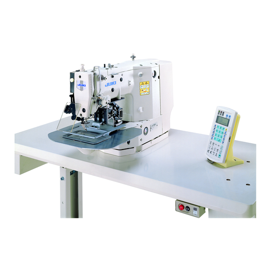
JUKI LK-1910 Engineer's Manual
Computer-controlled high speed bar tacking industrial sewing machine, computer-controlled high speed bar tacking industrial sewing machine with input function
Hide thumbs
Also See for LK-1910:
- Instruction manual (94 pages) ,
- Manual (6 pages) ,
- Handbook (272 pages)

Related Manuals for JUKI LK-1910


Summary of Contents for JUKI LK-1910
- Page 1 Computer-controlled High Speed Bar Tacking Industrial Sewing Machine LK-1910 / LK-1920 Computer-controlled High Speed Bar Tacking Industrial Sewing Machine with Input Function LK-1930 ENGINEER’S MANUAL 29326600 No.E329-03...
- Page 2 PREFACE This Engineer’s Manual is written for the technical personnel who are responsible for the service and maintenance of the machine. The Instruction Manual for these machines intended for the maintenance personnel and operators at an apparel factory contains operating instructions in detail. And this manual describes “Standard Adjustment”, Adjustment Procedures”, “Results of Improper Adjustment”, and other important information which are not covered in the Instruction Manual.
-
Page 3: Table Of Contents
2. CONFIGURATION ....................2 (1) Names of main unit ......................2 (2) Name of the switches on the operation box (LK-1910, 1920) ......... 3 (3) Names of the switches for the sewing machine operation (LK-1930) ......4 (4) Names of display indications (LK-1930) ................4 3. - Page 4 (1) Service pattern ........................48 (2) Patterns for users ......................48 5. MEMORY SWITCH .................... 50 (1) Operating method (LK-1910, 1920) .................. 52 1) How to start the memory switches ......................... 52 2) How to finish the memory switches ........................ 55 6.
- Page 5 1) Installing disk floating device ........................137 2) How to use disk floating device ........................137 15. TABLE OF ERROR INDICATION ( LK-1910, 1920) ........139 16. ERROR MESSAGE TABLE (LK-1930) ............140 17. POWER SWITCH CONNECTION DIAGRAM ..........142 (1) For 3-phase 200, 220 and 240V ..................
-
Page 6: Specifications
1. SPECIFICATIONS Specifications LK-1910 LK-1920 LK-1930 Sewing area X (lateral) direction 100 mm Y (longitudinal) direction 60 mm Max. sewing speed * 2,500 rpm (When sewing pitch is less than 3 mm.) Stitch length 0.1 to 10.0 mm (adjustable in 0.1 mm step) 0.1 to 12.7 mm (adjustable in 0.1 mm step) -
Page 7: Configuration
Manual pedal Power switch (Not provided with pneumatic type) Operation box (for LK-1910/20 only) Pedal switch (Shape of pneumatic type is different.) 1st step : Work clamp foot switch. 2nd step : Start switch Control box (for LK-1910/20 only) Air regulator (for pneumatic type only) −... -
Page 8: Name Of The Switches On The Operation Box (Lk-1910, 1920)
(2) Name of the switches on the operation box (LK-1910, 1920) Reset key Sewing LED Data indication Item selection LED Ready key Function key + / Feed forward key – / Feed backward key Selection key : Every time this key is pressed, the selection will be made as follows. -
Page 9: Names Of The Switches For The Sewing Machine Operation (Lk-1930)
(3) Names of the switches for the sewing machine operation (LK-1930) Sewing-ready LED Error LED Lights up when an error occurs. Lights up when sewing is ready. Power LED Thread winding key Lights up when the power is ON. Used for the bobbin thread winding. -
Page 10: Adjustments
3. ADJUSTMENTS (1) Adjustment of the main shaft components Standard Adjustment 1) Adjusting the play of the main shaft For the standard adjustment, clearance provided between the counter weight and the main shaft front bushing is 0.5 mm. 0.5mm Thread trimmer cam 2) Installing the main motor Flat section Machine arm... - Page 11 Adjustment Procedures Results of Improper Adjustment 1) Push counterweight 1 to main shaft front bushing 2, insert a clearance gauge of 0.5 mm between main shaft intermediate bushing 3 and thrust collar A 4 and fix thrust collar A 4 with screw while pressing it to main shaft intermediate bushing 3 side.
-
Page 12: Adjusting The Main Shaft Sensor
Standard Adjustment 3) Adjusting the main shaft sensor Slit plate passes the center. Face A (2) Adjusting the intermediate presser components (LK-1920, 1930) Standard Adjustment 1) Adjusting the position of the intermediate presser cam 1. Align engraved dot A of intermediate presser cam 1 with engraved dot B of the main shaft in the direction of rotation. - Page 13 Adjustment Procedures Results of Improper Adjustment 1) Remove sensor cover 2. ™ If the main shaft sensor is not 2) Fit the sensor installing base to face A. properly installed, the sensor Tighten setscrew 1 so that slit plate 3 passes the center of may be damaged or error may the sensor without interfering with each other and put the sensor ocur.
-
Page 14: Installing The Intermediate Presser Bar Guide Bracket Support Plate
Standard Adjustment 2) Installing the intermediate presser bar guide bracket support plate 1. Be sure to install intermediate presser bar guide bracket support plate 1 so that top end section A of intermediate presser bar guide bracket support plate comes in close contact with the bottom face of intermediate presser guide bracket 2. - Page 15 Adjustment Procedures Results of Improper Adjustment ™ If section A does not come in 1) Lightly press upward intermediate presser bar guide bracket support plate and tighten the screw in a state that section A close contact, the intermediate comes in close contact with the bottom face of intermediate presser bar guide bracket presser bar guide bracket 2.
-
Page 16: Height Of The Intermediate Presser Adjusting Screw
Standard Adjustment 4) Height of the intermediate presser adjusting screw Height of the intermediate presser adjusting screw is 24.5 mm for the standard adjustment value. 24.5 mm − −... - Page 17 Adjustment Procedures Results of Improper Adjustment 1) Turn intermediate presser adjusting screw 1 to adjust the height and fix it with intermediate presser adjusting nut 2. 2) When the height is increased, the pressing pressure is decreased. Caution : 1. Adjust the height within the range of 24.5 to 40 2.
-
Page 18: Adjusting The Position Of The Intermediate Presser Solenoid
Standard Adjustment 5) Adjusting the position of the intermediate presser solenoid A B Align 15 to 16 mm (3) Adjusting the wiper components Standard Adjustment 1) Adjusting the position of the wiper 1.5 mm Parallel 4 to 5 mm 7 to 8 mm − ... - Page 19 Adjustment Procedures Results of Improper Adjustment 1) Remove the motor cover and remove intermediate presser lifting spring 2 from intermediate presser lifting spring retainer 2) Tilt the machine head. ™ If face A enters further than face 3) Turn the hand pulley to bring the needle bar to its lower dead point.
-
Page 20: Adjustment Of The Shuttle Driver Shaft Components
(4) Adjustment of the shuttle driver shaft components Standard Adjustment 1) Adjusting the longitudinal position of the oscillator Shuttle drive shaft gear Face A 2) Adjusting the backlash of the oscillator gear 0.1 mm or less Face A 3) Removing the play of the shuttle driving shaft − ... - Page 21 Adjustment Procedures Results of Improper Adjustment 1) Loosen setscrews 1 and 2. ™ If the longitudinal position of the 2) When turning the main shaft several times, oscillator 3 moves oscillator is not correct, it will in the direction of arrow, and it moves naturally to the position c a u s e t h e s e i z u r e o f t h e without the load.
-
Page 22: Adjustment Of The Thread Trimmer Mechanism Components
(5) Adjustment of the thread trimmer mechanism components Standard Adjustment 1) Adjusting the thread trimmer cam 1. Position of the direction of the main shaft : Adjust the clearance between the main shaft thrust collar and thread trimmer cam 3 to 0.5 mm. 2. - Page 23 Adjustment Procedures Results of Improper Adjustment 1) Determine the position of thread trimmer cam 3, and tighten ™ Thread trimming failure will screw No. 1 1 of the thread trimmer cam from the upper side occur. ™ Lock of the sewing machine will of the sewing machine.
-
Page 24: Position Of The Thread Trimmer Shaft
Standard Adjustment Position of the thread trimmer shaft Make sure that the rear end of thread trimmer shaft 4 aligns with the processed face A of the sewing machine arm in the state that tension release pin 2 of tension release arm 1 is separated from tension release notch 3 (thread trimmer stopper support comes in contact with the section B of the sewing machine arm stopper.). - Page 25 Adjustment Procedures Results of Improper Adjustment 1) Loosen setscrew 6 in the cam installing link. (The thread ™ If thread trimmer shaft 4 is trimmer shaft is possible to rotate.) mitakenly adjusted, the receiving Loosen two setscrews 5 in the tension release arm thrust amount of thread trimmer shaft 4 collar.
-
Page 26: Position Of The Thread Trimmer Magnet Arm
Standard Adjustment 5) Position of the thread trimmer magnet arm 1. When thread trimmer magnet 3 draws, the clearance between the roller attaching face of cam installing link 4 and the cam face of thread trimmer cam 2 is 1 mm. 1 mm − ... - Page 27 Adjustment Procedures Results of Improper Adjustment 1) Loosen adjusting screw 1 in the thread trimmer magnet and ™ Thread trimmer roller enters the make thread trimmer magnet 3 draw in the direction of A at slit of thread trimmer cam, the approach run section of thread trimmer cam 2 [refer to 2) causing thread trimmer failure or Adjusting the thread trimmer link stopper screw, p.17].
-
Page 28: Position Of The Moving And Counter Knives
Standard Adjustment 6) Position of the moving and counter knives Position of the counter knife : Clearance between the counter knife and the needle hole guide is 0.5 mm. Position of the moving knife : Distance from the front end of the throat plate to the top end of the thread trimmer lever (small) is 18.5 mm before thread trimming action. - Page 29 Adjustment Procedures Results of Improper Adjustment ™ When the clearance is 0.5 mm 1) Position of the counter knife Loosen counter knife setscrews 1 to adjust it. or less : 2) Position of the moving knife When the moving knife pulls Loosen screw 2 to adjust it.
-
Page 30: Adjustment Of The Tension Release Components
(6) Adjustment of the tension release components Standard Adjustment 1) Installing position of the tension release notch Thread trimmer cam 2) Position of the tension release stopper When tension release arm 7 is moved in the direction A in the state that the cam installing link is separated from thread trimmer cam 6 (in the state that tension relase arm 7 comes in contact with tension release link 8), adjust the clearance between the periphery of thread trimmer cam 6 and tension release arm pin 5 to 1.2 mm. - Page 31 Adjustment Procedures Results of Improper Adjustment 1) Loosen two setscrews 1 in the tension release notch, and ™ Length of remaining needle move tension release notch 2 to the center of the long slit. thread after thread trimming will Then securely tighten two setscrews 1 to fix it. be shortened.
-
Page 32: Adjusting The Sensor Components
(7) Adjusting the sensor components Standard Adjustment 1) Mechanical origin 195 mm (63) Needle hole Y feed support shaft X feed support shaft Feed plate 2) Adjusting the Y origin sensor − −... - Page 33 Y feed support shaft become a straight line. occur. Fit the point by adjusting 2) Y origin sensor and 3) X origin sensor. * 1) Select “Test mode No. 2 Origin retrieval”. (For LK-1910/20 only) * 2) Simultaneously pressing in the operation panel, turn ON the power.
-
Page 34: Adjusting The X Origin Sensor
Standard Adjustment 3) Adjusting the X origin sensor − −... - Page 35 Adjustment Procedures Results of Improper Adjustment 1) Select “Test mode No. 2 Origin retrieval”. (For LK-1910/20 only) 2) Simultaneously pressing in the operation panel, turn ON the power. (For LK-1930 only) 3) Press in the operation panel. (For LK-1930 only) 4) Every time depressing the pedal, the origin is retrieved.
-
Page 36: Adjustment Of The Feed Mechanism Components
(8) Adjustment of the feed mechanism components Standard Adjustment 1) Adjusting the position of the X motor base Center of the hook driving shaft Center of the motor base Adjusting the positions of the X motor and the Y motor (adjusting the backlash of the driving gear) − ... - Page 37 Adjustment Procedures Results of Improper Adjustment 1) Loosen three setscrews 1, strongly push the X motor base in ™ If the pushing is not sufficient, the direction of arrow (a), and tighten again setscrews 1. the backlash of the gear will become large, and the accuracy (Caution) When removing setscrews 1 and the X motor base, of the needle entry will be...
-
Page 38: Installing The Feed Plate Support Plate
Standard Adjustment 3) Installing the feed plate support plate End face A 4) Installing the feed plate Flat section 45˚ 45˚ Fig. 1 − −... - Page 39 Adjustment Procedures Results of Improper Adjustment 1) Loosen two Y feed arm setscrews 1. ™ The load of the feed will become 2) Push Y feed shaft 2 in the direction of arrow f. large, causing the failure of the 3) Loosen three setscrews 3 in the feed plate support plate, and feed.
-
Page 40: Installing The Feed Bracket
Standard Adjustment 5) Installing the feed bracket Sewing area 30 mm 30 mm Center of needle 37 mm 37 mm (80.8) − −... - Page 41 Adjustment Procedures Results of Improper Adjustment 1) Select “Test mode No. 2 Origin retrieval”. (For LK-1910/20 only) ™ If the installing dimension is not proper, maximum sewing area 2) Simultaneously pressing in the operation panel, cannot be secured. turn ON the power. (For LK-1930 only) 3) Press in the operation panel.
-
Page 42: Adjusting The Bobbin Thread Winder Components
10.5 mm Intermediate presser cam stopper Intermediate presser cam Hand pulley gear (2 mm, LK-1920 • 1930) (50 mm, LK-1910) (10) Adjusting the presser components Standard Adjustment 1) Joining of the presser plate and the presser shaft (Solenoid type) − −... - Page 43 Adjustment Procedures Results of Improper Adjustment 1) Adjust the position of bobbin winder driving wheel 1 so that ™ If the clearance is small, it will the clearance provided between bobbin winder driving wheel cause worn-out of the bobbin 1 and arm cover installing face 2 should be 10.5 mm, and thread winder components or tighten setscrews 3 (2 places).
-
Page 44: Adjusting The Position Of The Presser Shaft Guide (Solenoid Type)
Standard Adjustment 2) Adjusting the position of the presser shaft guide (Solenoid type) 3) Adjusting the presser cylinder (Pneumatic type only) Presser cylinder − −... - Page 45 Adjustment Procedures Results of Improper Adjustment 1) Loosen two attaching screws 1. Apply grease to the inside of ™ If the adjustment is not correct, presser shaft bushing 4 and the inside of presser shaft guide t h e p r e s s e r s h a f t g u i d e 3, and fix presser shaft guide 3 to the presser shaft in the interferes with the presser shaft state that no load is applied to presser shaft 2.
-
Page 46: Height Of The Slider (Pneumatic Type Only)
Standard Adjustment 4) Height of the slider (Pneumatic type only) 1. Closely attach the top end of slider 2 to presser plate sheet 3. 5) Adjusting the speed controller 1. Lowering speed of the presser is properly adjusted. 2. When using as 2-step presser, lowering speed of the left and right can be adjusted. Knob 2 Left Right... - Page 47 Adjustment Procedures Results of Improper Adjustment 1) Adjust the height of slider 2 using four setscrews 1. To position ™ If the height of the slider is the height, press slider 2 to presser plate sheet 3 in the state incorrect, malfunction of the feed that feed bracket 3 is lightly lifted in the c direction when the will occur.
-
Page 48: Adjustment Of The Sewing Components
(11) Adjustment of the sewing components Standard Adjustment Adjusting the position of the shuttle upper spring Align the center of the needle with the center of slit width C for the lateral position. Align the rear end of the needle with angle section A for the longitudinal position. (Caution) If there is a scratch on section B polish there with buff or the like as it will cause thread breakage, hangnail of thread, stain on thread, etc. - Page 49 Adjustment Procedures Results of Improper Adjustment ™ If the shuttle upper spring is slid 1) Remove the feed bracket, feed plate and throat plate, and adjust with screws 1. laterally or longitudinally, needle thread will be caught in the (Caution) The lateral position will vary when the shuttle is shuttle.
-
Page 50: Shuttle Felt
Standard Adjustment 2) Shuttle felt Three pieces of shuttle felt 1 are inserted into the hole of the shuttle race. When setting the inner hook and rotating it along with the shutle race, make sure whether the felt is applying a load. Race Shuttle 3) Shape of the shuttle race ring... - Page 51 Adjustment Procedures Results of Improper Adjustment 1) If shuttle felt 1 is protruding, or is replaced with a new one, ™ If the shuttle felt is protruding, a push it into the hole with tweezers or the like. rotating load is applied to the inner hook, causing stitch failure.
-
Page 52: List Of Replacement Components For Standard And Heavy-Weight Materials
Standard Adjustment 4) List of replacement components for standard and heavy-weight materials << Replacement components for LK-1910, -1920, and -1930 >> Type Part No. Parts S type (Standard) H type (Heavy-weight materials) Needle DPx5#14 DPx17#18 Needle bar B1401210000 ← Needle bar thread guide... -
Page 53: Stitching Pattern
DATA MAIN circuit board ™ Three kinds of service patterns (No. 50, 51 and 52) are registered in LK-1910 / 20 beforehand. ™ Data are registered in SYSTEM_ROM of 1. ™ Patterns in SYSTEM_ROM are fixed data and cannot be edited with the input device (PGM-20) or the like. - Page 54 4) Storage medium ™ Standard DATA_ROM (U21) 256k bit EEP-ROM (58C256) Part No. : HL011940000 ™ In addition to the standard DATA_ROM, the following ROM is available. 1) Data ROM of existing AMS-205, 206. 64k bit EEP-ROM (58C65) * When using the above ROM, change of the switch on MAIN circuit board is required. (Change the jumper post of 3 from S to ○...
-
Page 55: Memory Switch
5. MEMORY SWITCH (LK-1910, 1920) ™ Purpose of the memory switch ..The memory switches are able to set the various performance of the sewing machine by means of programming. The contents are separated in the user level (U) and the service level (S). - Page 56 Selection of control of thread trimming device 0 : Yes (In any case, thread trimming is not possible.) 1 : No Selection of model at the time of delivery 10 : LK-1910 / S Depending on the (Initial setting) 11 : LK-1910 / A specifications...
-
Page 57: Operating Method (Lk-1910, 1920)
(1) Operating method (LK-1910, 1920) 1) How to start the memory switches Step Operation method Indication Explanation Pressing key and READY READY RESET RESET Keep key, turn ON the power pressing. switch. (Start of the level 1) Immediately after turning Turn ON the power switch. - Page 58 2 Operation when the indication is “0 3 - -”. Step Operation method Indication Explanation FORWARD BACK Press down 2 -1 FORWARD BACK to select the indication No. 3. Sewing LED SEWING READY Lights up. Press down key to light READY 2 -2 up Sewing LED.
- Page 59 3 Operation when the latter second digit is “–” and first digit is “Numeral” Step Operation method Indication Explanation [Ex.] When the indication No. Press down is No. 04. FORWARD BACK FORWARD BACK 3 -1 key to select the indication No.
-
Page 60: How To Finish The Memory Switches
潺 Operation when the indication section is “99.” Step Operation method Indication Explanation [Ex.] When the indication No. Press down is No. 99. FORWARD BACK FORWARD BACK 潺 -1 key to select the indication No. 99. Sewing LED SEWING READY Lights up. -
Page 61: How To Use The Memory Switch (Lk-1930)
6. HOW TO USE THE MEMORY SWITCH (LK-1930) (1) Memory switch The memory switchs mean switches which are able to set the various performances of the sewing machine by means of programming. There are two different start levels, level 1 and level 2, for the memory switches according to the function level as described below. -
Page 62: How To Start The Memory Switches
How to start the memory switches Perform the start of the memory switches as described below. [How to start the level 1] [How to start the level 2] Step 1 : Turn ON the power switch while keeping the Step 1 : Turn ON the power switch while keeping the key on the operation panel held depressed. -
Page 63: Write-In Of The Contents Of Setting
(5) Write-in of the contents of setting After setting the respective items, write in the memory the contents of setting following the way of operation as described below. After finalizing the change of all settings, press key. The display on the operation panel will be indicated as follows. >... -
Page 64: Writing/Reading Of The Contents Of The Memory Switches Onto The Floppy Disk
(6) Writing/reading of the contents of the memory switches onto the floppy disk It is possible to write the contents of the memory switches onto the floppy disk or to read the memory switches written onto the floppy disk. Writing/reading of the memory switches can be performed by the operation procedures as shown in the figure below. -
Page 65: Description Of The Memory Switches (Lk-1930)
7. DESCRIPTION OF THE MEMORY SWITCHES (LK-1930) NOTE : The contents of the memory switches may vary due to the revision of the system ROM. (Following contents are applied to the Revision 008 of the System ROM.) (1) Setting of the language indication Function No. - Page 66 (3) Jog function setting Function No. : 003 Function : Jog mode is set. Item : 1 Mode specification (Set level 1) [Contents] Moving of the feeding frame cannot be made with jog keys, PARA [Contents] A sewing pattern can be moved to a specified position by using jog keys →...
- Page 67 (4) Mechanical origin retrieval Function No. : 007 Function : This function sets the operation of the mechanical origin retrieval. Item : 1 Setting the operation of each sewing cycle (Set level 2) [Contents] Not operative : Initial setting Indication [Contents] Origin retrieval is made for each sewing cycle.
- Page 68 (7) Setting of pattern data reading operation Function No. : 010 Function : Pattern data reading operation mode is set. Item : 1 Pattern data reading operation setting (Set level 2) SETUP [Contents] Pattern data can be read under the sewing setting state. (the sewing LED goes out.) : Initial setting Indication READY...
- Page 69 (10) Selection of thread trimming after turning ON the temporary stop switch Function No. : 013 Function : This function sets the thread trimming operation when operating the temporary stop switch. Item : 1 Thread trimming setting (Set level 1) AUTO [Contents] Thread trimmer automatically actuates.
- Page 70 (14) Bank function setting Complementary explanation → P.91 Function No. : 021 Function : This function sets bank operation. Item 1 : With/without the bank operation and setting of the number of banks (Set level 2) [Contents] Bank function is ineffective. (Bank function does not work.) : Initial setting Indication 1 to 16 [Contents] This function sets the number of banks to be used.
- Page 71 (16) Setting of F1 . F2 keys Function No. : 023 Function : Setting of F1 and F2 keys on the operation panel can be made. This function can set the keys which are used often during inputting. Item : 1 Setting of F1 key (Set level 1) [Contents] Not registered.
- Page 72 (18) Feed control Function No. : 029 Function : Setting of the synchronized control of the sewing machine and the X-Y feed Item : 1 Setting of the sewing pitch to the sewing speed (Set level 1) [Contents] 2500 r.p.m. / 3.0 mm : Initial setting [Contents] 2000 r.p.m.
- Page 73 (19) Feeding frame control 1 Complementary explanation → P.99 Function No. : 030 Function : Feeding frame device setting Item : 1 Setting at the automatic opening/closing (Set level 2) 0 to 99 [Contents] Action sequence is set when the feeding frame automatically opens/ Indication closes in case of operating the preparation key, threading key, etc.
- Page 74 (21) Pedal control 1 Complementary explanation → P.102 Function No. : 032 Function : Setting of the pedal operation mode Item : 1 Setting of the latch operation of the pedal 1 (Set level 1) Setting of the operation mode of the pedal 1 (right-side pedal when using the PK-47 device) FLIP ※...
- Page 75 (24) Intermediate presser control Function No. : 035 Function : Setting of the intermediate presser operation mode Item : 1 Intermediate presser control (Set level 1) [Contents] Intermediate presser is operative. (The intermediate presser comes down by the sewing data when the machine runs.) : Initial setting TRIAL [Contents] Intermediate presser is operative.
- Page 76 (27) Thread breakage detector control Function No. 038 Function : Thread breakage detector operation mode setting Item : 1 Device control (Set level 1) [Contents] The thread breakage detecting device is ineffective. Indication [Contents] The thread breakage detecting deviceon effective. Initial setting Item : 2 Setting the number of stitches required to stop the machine (at the sewing start) (Set level 2) 0 to 15...
- Page 77 (31) Thread trimming control Function No. : 044 Function : Thread trimmer setting Item : 1 Device control (Set level 2) [Contents] Thread trimming operation is not made in any case. (Thread trimming operation is not made at the time of temporary stop and thread breakage.) Indication [Contents] Thread trimming operation is made.
- Page 78 (35) Sewing machine speed control 2 Function No. : 051 Function : Starting speed (after 3 stitches to after 4 stitches) of the sewing machine is set. Item : 1 Soft-start 4 2 to 25 X 100 r.p.m [Contents] Speed after 3 stitches when the sewing machine is actuated is set. Indication (Initial setting 25) Item : 2 Soft-start 5...
- Page 79 (38) Magnet type wiper operation time function Function No. : 054 Function : Time setting of the magnet type wiper operation Item : 1 Wiper-on time (Set level 2) Indication 0 to 999 ms [Contents] Setting of the wiper ON time : Initial setting 50 Item : 2 Wiper return waiting time (Set level 2) 0 to 999 ms...
- Page 80 (41) Feeding frame connection setting 1 : This function is not used with the standard machine. Function No. : 063 Function : Setting of the output device of the drive signal of feeding frame Item : 1 Setting of the feeding frame 1 (Set level 2) [Contents] No connection 1 to 16...
- Page 81 (43) Intermediate presser connection setting : This function is not used with the standard machine. Function No. : 065 Function : Setting of the output device of the drive signal of intermediate presser lifter Item : 1 Intermediate presser lifter setting (Set level 2) [Contents] No connection 1 to 16...
- Page 82 (46) Bobbin thread replacing device connection setting : Not used. Function No. : 072 Function : Setting of the output/input devices of the bobbin thread replacing device Item : 1 Setting of the signal output of the start of replacement (Set level 2) [Contents] No connection : Initital setting 1 to 16...
- Page 83 (49) Bank selection connection setting : This function is not used with the stndard machine. Supplementaly explanation : P91 Function No. : 075 Function : Setting of the number of terminals when the bank selection is made by the external signal. Item : 1 Setting of the number of terminals for bank selection (Set level 2) [Contents] Can be used up to 2 patterns.
- Page 84 (51) External output terminal connection setting 2 : This function is not used with the standard machine. Function No. : 077 Function : Setting of the output device of the external output terminal Item : 1 Output terminal 3 setting (Set level 2) [Contents] No connection : Initial setting 1 to 16...
- Page 85 (53) External output terminal connection setting 4 : This function is not used with the standard machine. Function No. : 079 Function : Setting of the output device of the external output terminal Item : 1 Output terminal 9 setting (Set level 2) [Contents] No connection : Initial setting 1 to 16...
- Page 86 (56) External input terminal connection setting 1 : This function is not used with the standard machine. Function No. : 082 Function : Setting of the input device of the external input terminal Item : 1 Input terminal 0 setting (Set level 2) [Contents] No connection : Initial setting 1 to 16...
- Page 87 (58) External input terminal connection setting 3 : This function is not used with the standard machine. Function No. : 084 Function : Setting of the input device of the external input terminal Item : 1 Input terminal 6 setting (Set level 2) [Contents] No connection : Initial setting 1 to 16...
- Page 88 (60) External input terminal connection setting 5 : This function is not used with the standard machine. Function No. : 086 Function : Setting of the input device of the external input terminal Item : 1 Input terminal 12 setting (Set level 2) [Contents] No connection : Initial setting 1 to 16...
- Page 89 (64) Needle cooler control Function No. : 109 Function : Needle cooler control is set. Item : 1 Whether needle cooler control is provided or not is set. (Set level 2) [Contents] Output signal for solenoid valve is not transmitted : Initial setting Indication [Contents] Output signal for solenoid valve is transmitted.
-
Page 90: Initialization Of The Memory Switch (Lk-1930)
8. INITIALIZATION OF THE MEMORY SWITCH (LK-1930) (1) HOW TO INITIALIZE When the first setting state of the memory switch is not known, or the sewing machine fails to operate well, the contents set in the memory switch can be restored to the state at the time of delivery by means of the following operation. -
Page 91: Table Of The Initial Setting
(2) TABLE OF THE INITIAL SETTING The initial value of the memory switch is as shown in the following table. Initial setting 1930 1930 1930 1930 Function Start Function Item SS / HS SA / HA SS / HS SA / HA level -FU02S -FU02S... - Page 92 Initial setting Function 1930 1930 1930 1930 Start Function Item SS / HS SA / HA SS / HS SA / HA level -FU02S -FU02S ← ← ← Chuck error detection 1. Control ← ← ← Intermediate presser 1. Control ←...
- Page 93 Initial setting Start 1930 1930 1930 1930 Function Function Item SS / HS level SA / HA SS / HS SA / HA -FU02S -FU02S Bobbin thread 1. Output terminal number of replacement start signal ← ← ← replacement device 2.
- Page 94 Initial setting 1930 1930 1930 1930 Function Start Function Item SS / HS SA / HA SS / HS SA / HA level -FU02S -FU02S Pedal control 3 1. Setting of pedal 1 operation active HIGH HIGH 2. Setting of pedal 2 operation active ←...
-
Page 95: Complementary Explanation Of Function Nos. (Lk-1930)
9. COMPLEMENTARY EXPLANATION OF FUNCTION NOS. (LK-1930) (1) Fixed retracted position setting (Function No. 003) Regardless of the 2nd origin in the sewing pattern, a 2nd origin (fixed retracted position) common to each sewing pattern can be set with the memory switch. When the item 2 “Fixed retracted position setting”... -
Page 96: How To Use The Bank Function (Function No. 021 And 075)
(2) How to use the bank function (Function No. 021 and 075) Bank function The bank function means that plural patterns Memories inside the in the floppy disk can be stored in the memory sewing machine of the sewing machine main unit and instantly Read-in Bank 1 change the patterns from the external signal... - Page 97 Item 2 : Setting of read-in method [Consecutive number read-in] (SEQ) Patterns are read in the memory of the sewing machine side from bank No. 0 by turns in the order of the specified pattern numbers At this time, the pattern desired to be read in should be stored in the floppy disk with consecutive pattern numbers.
- Page 98 In case the set value is 1 in the item 1 In this case, if “1” is set in the item 2, use the signal from the input terminal 1 and two bank numbers can be used by turning ON/OFF. Also, if “2”...
- Page 99 Bank No. Input signal Table 3 [Form of connector for signal input] Connector forms used for the input connectors are as follows : Manufacturer name Name Manufacturer form JUKI Part No. MOREX Receptacle 5557-24R HK034610024 MOREX Female terminal 5556T2L HK03464000A −...
- Page 100 [Setting flow chart when using the bank function] Flow chart until the bank function is set is as shown in Start the memory switch the figure left. Change the contents of function No. Write-in of the changed contents After completing the write-in, turn OFF the power Bank mode starts by starting under the normal mode.
-
Page 101: Combination Function
(3) Combination function Reading plural patterns from the floppy disk and sewing in a combined state using the combination function can be made. <Example 1> Correspond the origins of both patterns with each other and combine the two patterns. <Example 2> Correspond the origins of both patterns with each other including inserting a temporary stop and combine the two patterns. - Page 102 Starting method of the combination function There are two starting methods of the combination function. Use the starting methods according to the sewing condition. <Starting method 1> In case the change of combination pattern is frequently made, change the setting of memory switch so that the combination function always actuates.
- Page 103 <Starting method 2> In case of sewing the same combined patterns for a long period of time, start the combination function using the operation panel. Pressing the Pressing the Pressing the Pressing the keys on the panel, keys on the panel, keys on the panel, keys, turn ON the turn ON the power.
-
Page 104: How To Set The Sequence Of The Feeding Frame Operation (Function Nos. 030 To 033, 98, 99)
(4) How to set the sequence of the feeding frame operation (Function Nos. 030 to 033, 98, 99) The LK-1930 can change the operating way of the feeding frame and pedal using the memory switch. The setting of the desired operation of the feeding frame and pedal can be made by changing the function Nos. - Page 105 Item 3 : Selects the operation order of the feeding frame when opening / closing by the pedal after the temporary stop by the temporary stop command. Refer to the table 2. [Memory switch setting level table 2] Setting Contents Priority order Description None...
- Page 106 Function No. 31 Feeding frame control (2) This function sets the release of the feeding frame when the sewing is completed. Item 1 : Control of the release of the feeding frame at the time of completion of the sewing. This function sets the operation order when the feeding frame goes up after completing the sewing.
- Page 107 Function No. 32 Pedal input control (1) This function sets the way of pedal operation. Item 1 : Sets the pedal operation of the pedal 1 (feeding frame, right). Solenoid type : Non latch Set value FLIP or LATCH (Refer to the table 4.) Initial setting : Pneumatic type : Latch Item 2 : Sets the pedal operation of the pedal 2 (feeding frame, left).
- Page 108 Function No. 98 Pedal input control (3) Setting of pedal operating method is performed. Item 1 : Pedal operation active of the pedal 1 (feeding frame, right) is set. Set value : LOW/HIGH Intial setting Item 2 : Pedal operation active of the pedal 2 (feeding frame, left) is set. (Pneumatic type only) Set value : LOW/HIGH Initial setting : LOW Item 3 : Pedal operation active of the pedal 3 (stroke presser) is set.
-
Page 109: Test Mode (Lk-1910, 1920)
10. TEST MODE (LK-1910, 1920) ™ Purpose of the test mode This mode is set to facilitate the electrical check for the maintenance work. ™ List of items of the test mode Indication No. Item Description State of input of the switch and the sensor will be indicated by 8 LEDs. -
Page 110: Operating Method
(1) Operating method 1) How to start the test mode Step Operation method Indication Explanation READY Pressing key and RESET READY key, turn ON the power RESET Keep switch. pressing. (Starting of the user level Turn ON the of memory switch) power switch. - Page 111 Indicating output test Order of the indicating output test after moving to the test mode is shown as follows. Sewing LED Lights up SEWING Sewing LED Lights up SEWING − −...
-
Page 112: How To Check Each Test Program No
2) How to check each test program No. 1 CP-1 (input signal check) State of input of switches and sensors is indicated on the 8 LEDs. LED indication table ..Table of LED assignment of each switch and sensor Input line Kind of LED THREADING WINDER... - Page 113 Indicating section (input line No.) Explanation Checking measure State of the input line No. 3 switch will be indicated on LED. [Example] Check the presser lifter switch. Presser lifter switch [Example] Check the start switch. Start switch Update of the input line No. 3 to 4 Simultaneously (Refer to the adjustment of the sensor press.
- Page 114 2 CP-2 (origin retrieval) For origin adjustment, state of origin retrieval, feeding operation and origin sensor will be indicated. Step Indicating section Checking measure Explanation SELECT JOG movement of the X/Y axes can be changed by pressing down the key. SELECT “...
- Page 115 3 CP-3 (continuous operation) Performs the initial setting of the operation conditions, and moves to the continuous operation mode. Step Indicating section Checking measure Explanation A time of pause is set by pressing FORWARD BACK down FORWARD BACK Setting range : 0 to 9,900 ms (in a unit of 100 ms) By pressing down key, the...
- Page 116 4 CP-4 (checking the number of revolutions of main shaft) Output of the specified number of revolutions is made and the actual number of revolutions is indicated. Step Indicating section Checking measure Explanation Initial state “SPEED” LED of the setting item lights up.
- Page 117 If following operation is made when the step is above-mentioned “step 4”, the indication can be changed to the indication of the specified number of revolutions. Indicating section Checking measure Explanation The output is changed to the output of the SELECT specified number of revolutions by pressing down...
-
Page 118: How To Finish Test Mode
5 CP-5 (Solenoid and solenoid valve output check) Checks the output of solenoid and solenoid valve. Output No. Table Output No. Solenoid and solenoid valve Feeding frame solenid (and solenoid valve, right / left ..depending on pedal specifications) Feeding frame solenoid valve, right Feeding frame solenoid valve, left Intermediate presser solenoid Inversion (thread controller No. -
Page 119: Test Mode (Lk-1930)
11. TEST MODE (LK-1930) How to start the test mode 1) Pressing the keys, turn ON the power. TEST MODE 1 XY SNS 4 AGING 2 INPUT 5 SPEED 3 OUTPUT Display of test mode selection 2) If the display is shown, input the function Nos. ( of the test mode from the operation panel. - Page 120 [Explanation of the indication] Indication 1 Indication of key code from operation panel Two digits of the number corresponding to the key will be shown when operation panel is pressed. Codes corresponding to each key are as shown in the following table. Switch name Code Switch name...
- Page 121 Indication 4 Sensor input X and Y sensors, and external input signal are shown. The indication is as follows. * * * * X origin “0” will be indicated when the sensor is covered. Y origin : When temperature rise is detected, “1” is indicated. Thermostat : When the signal is transmitted, “1”...
- Page 122 (2)-3 Function No. 3 : Output check function Operation of the devices can be confirmed by outputting signals to the respective outputs from operation panel. 1) Select the key when selection of the test mode is OUTPUT CHECK shown. 00000000 [Display indication] 1 Step indication Output check is composed of four steps from OUTPUT CHECK...
- Page 123 (2)-4 Function No. 4 : Aging function This function actuates under continuous operation mode of the sewing machine. 1) Input the key when the test mode selection is shown No. 000 AGING on the display. XS : 1000 YS : 1000 BC : 000 PC : 0000 2) Set the pattern No.
-
Page 124: Parts Grease Or Lock-Tight Paint Is Applied
12. PARTS GREASE OR LOCK-TIGHT PAINT IS APPLIED Apply grease periodically (one time/half yearly) to the parts shown in the figure. Be sure to apply grease to each sliding parts not shown in the figure when overhauling or re-assembling. THREAD TRIMMING COMPONENTS MAIN SHAFT COMPONENTS LOCK-TITE 601 LOCK-TITE 601... - Page 125 INTERMEDIATE PRESSER COMPONENTS LOCK-TITE 241 LOCK-TITE 241 PRESSER COMPONENTS Grease LOCK-TITE 241 LOCK-TITE 638 Grease (Bottom face) Grease (Bottom face) − −...
-
Page 126: Presser Dimensions
13. PRESSER DIMENSIONS Feed plate ø4 LK-1910, 20 Sewing area Origin AMS-206 sewing area − −... - Page 127 MEMO − −...
-
Page 128: How To Use Optionals
14. HOW TO USE OPTIONALS (1) Needle cooler (Pneumatic type only) Standard Adjustment 1. When synthetic thread is used and thread breakage or stitch skipping due to needle heat occurs, use the needle cooler to cool needle. 1) Installing procedure of the needle cooler 1 Installing the needle cooler compl. - Page 129 Adjustment Procedures Results of Improper Adjustment 1) Insert air tube 2 into needle cooler compl. 1. 2) As shown in Fig. 1, lay air tube 2 and install needle cooler compl. 1 to tap A of eye guard installing plate 5 through washer 3 with setscrew 4.
-
Page 130: How To Use The Needle Cooler
Standard Adjustment 2 Installing the solenoid valve Caution (Caution) In case of LK-1930, the connector Connector marker J79 connecting No. varies in accordance with the memory switch setting. 2) How to use the needle cooler ™Needle cooler blows air while the main shaft is rotating. − ... - Page 131 6) Insert pin contact 7 of solenoid valve connector asm. 6 into the connector (connector marker J79) of the solenoid valve cable asm. (Caution) 1. In case of LK-1910 and LK-1920, when inserting pin contact 7 into the connector, insert “+” side (red) of solenoid valve connector asm. 6 into No.
-
Page 132: Inverting Clamp Device (Fu-02S, Fu-02L)
(2) Inverting clamp device (FU-02S, FU-02L) Standard Adjustment 1) Installing the inverting clamp device − −... - Page 133 Adjustment Procedures Results of Improper Adjustment 1) Remove four setscrews 1 and two oval counter-sunk screws ™ If grease is not applied when 2 and remove cloth presser slide plate lid 3. installing, 5 and 6 may not 2) Remove work clamp feet (left/right) 4 installed as standard move.
-
Page 134: How To Use The Inverting Clamp Device
1. When using the inverting clamp device, it is required to change the mode to the inverting clamp mode with the memory switch. (Refer to Instruction Manual for LK-1910 / 20.) (1) When creating the pattern, be careful about the contact of clamp shaft with needle. - Page 135 Adjustment Procedures Results of Improper Adjustment 1) When sewing is completed, crank shaft is inverted to the original ™ When the number of optional state and presser goes up. To prevent interference with needle, inverting rotations is the even it is recommended to input a point being 10 mm away from the number, the crank shaft does not center of crank shaft as the 2nd origin when creating a pattern.
-
Page 136: Tension Controller No. 3 (Pneumatic Type)
(3) Tension controller No. 3 (Pneumatic type) Standard Adjustment 1. In case thread-tightness is partially not good due to difference in cloth thickness, hitch stitch, etc., needle thread tension can be increased at desired position by using the tension controller No. 3. 1) Installing the tension controller No. - Page 137 Adjustment Procedures Results of Improper Adjustment 1) Loosen setscrew 1 and remove thread guide plate 2. 1) Install air tube 3 to tension controller No. 3 4 and install the controller almost horizontally to the machine arm with setscrew * Refer to Fig. 1 for threading. (Caution) 3, 4 and 5 only are included in tension controller No.
- Page 138 Standard Adjustment 1 Installing the solenoid valve Caution (Caution) In case of LK-1930, the connector Connector marker J79 conecting No. varies in accordance with the memory switch setting. − −...
- Page 139 6) Insert pin contact 7 of solenoid valve connector asm 6 into connector (connector marker J79) of the solenoid valve cable asm. (Caution) 1. In case of LK-1910 and LK-1920, when inserting pin contact 7 into the connector, insert “+” side (red) of solenoid valve connector asm. 6 into No.
-
Page 140: How To Use The Tension Controller No. 3
2) How to use the tension controller No. 3 1 Confirmation of the memory switch 2 Creation of the pattern (LK-1910, 1920) ™ To drive the tension controller No. 3, it is required to input an inverting point in the sewing pattern. - Page 141 Adjustment Procedures Results of Improper Adjustment 1) In case of LK-1910 and LK-1920, when installing of the tension controller No. 3 is completed, set No. 31 (selection of inverting clamp and tension controller No. 3) of memory switch to “1” (0 : inverting clamp, 1 : tension controller No.
-
Page 142: Disk Floating Device For Basting Stitch
(4) Disk floating device for basting stitch Standard Adjustment 1) Installing disk floating device 2) How to use disk floating device − −... - Page 143 1 When performing jump feed, the disk floating device is actuated and the needle thread tension is released. ™ In case of LK-1910 and LK-1920 If memory switch function (selection of basting) No. 27 is set 0 → 1, pattern sewing data is read for jump feed and curved point for sewing, and they are operated respectively.
-
Page 144: Table Of Error Indication ( Lk-1910, 1920)
− −... -
Page 145: Error Message Table (Lk-1930)
16. ERROR MESSAGE TABLE (LK-1930) Error No. Indicator lamp Error description How to reset ServoMotor Alert Main shaft motor failure After turning OFF the switch, remove the trouble. S e r v o M o t o r F e e d e r Timing of main shaft and feed is not correct. - Page 146 How to reset Error No. Indicator lamp Error description Correct the pattern while it is input. Travel Limit Correct After computation in case of offset, 2-line Pattern sewing, etc., this occurs when the travel limit is over. Make sure the external input signal. Return Wait For Input Timeout External input signal is not input within the to the sewing start point with the return-to-...
-
Page 147: Power Switch Connection Diagram
17. POWER SWITCH CONNECTION DIAGRAM (1) For 3-phase 200, 220 and 240V Light blue White Table Plug side Green / Yellow Control box side Green Brown Black (2) For single-phase 100V, 110V and 120V 200V, 220V and 240V Light blue Light blue Table Plug side... -
Page 148: For 3-Phase 220V, 240V, 380V, 400V And 415V
(3) For 3-phase 220V, 240V, 380V, 400V and 415V Table Light blue Green / Yellow Brown Black Black Green / Yellow Light blue Control box side Plug side − −... -
Page 149: For Single-Phase 220V, 240V, 380V, 400V And 415V
(4) For single-phase 220V, 240V, 380V, 400V and 415V Black Light blue Table Black Black Green / Yellow Control Green / Yellow box side Plug side Green / Yellow Black Brown − −... -
Page 150: Connection Of The Power Plug
18. CONNECTION OF THE POWER PLUG (1) Overseas market : 100V series 200V series 1 φ 100V (Single phase 100V) , 1 φ 200V (Single phase 200V) When changing the voltage used, it 1 φ 110V (Single phase 110V) , 1 φ 220V (Single phase 220V) is nessary to change the wiring of 1 φ... -
Page 151: Overseas Market : 380V Series
(2) Overseas market : 380V series 3 φ 220V (3-phase 220V) 1) 3-phase When changing the voltage used, it is necessary to 3 φ 240V (3-phase 240V) change the wiring of the terminal board. Refer to 3 φ 380V (3-phase 380V) “voltage change-over of 220 to 415V”. -
Page 152: Change Of The Power Voltage
19. CHANGE OF THE POWER VOLTAGE (1) Change of the voltage from 100 to 240 V For the 100 and 200 V specifications, Green (White) Green (Blue) power voltages as shown on the Input voltage Remarks Terminal No. right table can be used. Refer to (Note 1) However, when 100, 110 and 120 V are used, “voltage-change cord”... -
Page 153: Maintenance And Inspection
20. MAINTENANCE AND INSPECTION (1) Replacing the printed circuit boards Types of printed circuit boards 1 MAIN circuit board (Control box) 2 SERVO circuit board (Control box) 3 PMDC circuit board (Control box) (For LK-1930 only) 4 POWER circuit board (Control box) 1) MAIN circuit board Acts as the brain of this machine and outputs the control signals to control the floppy disk driver unit, and to follow the program to operate the sewing machine head and the operation panel. -
Page 154: Power Circuit Board
4) POWER circuit board This circuit board supplies voltage to each unit in the control box. 1 Turn OFF the power switch, and open the control box cover. 2 Remove all connectors (J30 to J38) from the POWER circuit board. 3 Remove four nuts from the underside of the control box and remove the circuit board as shown in the figure below. -
Page 155: Troubles And Corrective Measures
– 150 –... - Page 156 – 151 –...
-
Page 157: With Regard To Sewing
– 152 –... - Page 158 – 153 –...
- Page 159 – 154 –...
- Page 160 – 155 –...
- Page 161 – 156 –...
- Page 162 – 157 –...
- Page 163 – 158 –...
-
Page 164: Electrical Parts (Also, Refer To Block Diagram.)
– 159 –... - Page 165 – 160 –...
- Page 166 – 161 –...
- Page 167 – 162 –...
- Page 168 – 163 –...
- Page 169 – 164 –...
- Page 170 – 165 –...
-
Page 171: Curcuit Diagram
22. CIRCUIT DIAGRAM (1) Block diagram (LK-1910, 1920) (1A) UDET U DET AIR SW J20 (RED) X ORG AIR OPRE - R J21 (YELLOW) Y ORG Operation TH BRK AIR OPRE - L circuit EM STP board asm. FU-02S (L) -
Page 172: Block Diagram (Lk-1930)
(2) Block diagram (LK-1930) (J4) (P4) Machine head grounding cable asm. Operation panel (J20) (P20) X ORG sheet (J21) (P21) Y ORG TH BRK (J22) (P22) EM STP Machine head sensor relay cable asm. OUT-P SOL (J13) (P13) U DET Operation (1_B) circuit board... -
Page 173: Power Circuit Diagram A (Lk-1910, 1920)
(3) Power circuit diagram A (LK-1910, 1920) YELLOW +24V ORANGE +36V BLACK MAIN PCB BLACK PANEL BLUE WHITE +85V LIGHT BLUE WHITE +85V BROWN POWER SOURCE GREEN/YELLOW 27 28 7 14 29 30 GREEN/YELLOW 27 28 7 14 29 30... -
Page 174: Power Circuit Diagram A (Lk-1930)
(4) Power circuit diagram A (LK-1930) BLACK YELLOW +24V ORANGE +36V MAIN PCB BLACK BLACK PANEL LIGHT BLUE 27 28 7 14 29 30 4 10 12 BROWN POWER SOURCE GREEN/YELLOW 4 10 12 27 28 7 14 29 30 GREEN/YELLOW +24V WHITE... -
Page 175: Power Circuit Diagram B (Lk-1910, 1920)
(5) Power circuit diagram B (LK-1910, 1920) YELLOW +24V ORANGE +36V BLACK MAIN PCB BLACK BLUE PANEL LIGHT BLUE WHITE +85V WHITE +85V BROWN POWER SOURCE GREEN/YELLOW 27 28 7 14 29 30 GREEN/YELLOW 27 28 7 14 29 30... -
Page 176: Power Circuit Diagram B (Lk-1930)
(6) Power circuit diagram B (LK-1930) BLACK YELLOW +24V ORANGE +36V MAIN PCB BLACK BLACK PANEL LIGHT BLUE 6 9 2 4 10 12 27 28 7 14 29 30 BROWN POWER SOURCE GREEN/YELLOW 6 9 2 4 10 12 27 28 7 14 29 30 GREEN/YELLOW +24V... -
Page 177: Head Sensor Circuit Diagram
TH BREAK [N] BLACK ORANGE TH BREAK WHITE SW-NC SW-COM BLUE EM STP BLACK GRAY P4 (WHITE) PINK LIGHT BLUE WHITE PURPLE BLACK Common to LK-1910, 1920, and 1930 (Caution) 1. Numerals in are common to LK-1910, 1920 and 1930. − −... -
Page 178: Solenoid Valve Circuit Diagam
(8) Solenoid valve circuit diagam LK-1910, 1920 +24V +24V BLACK – AIR OPRE-R (N) AIR OPRE-R (N) +24V +24V BLACK AIR OPRE-L (N) – AIR OPRE-L (N) +24V AIR 1 +24V Needle cooler (OPTION) BLACK – AIR 2 +24V FU-02S (L) or Tension controller No.3 (OPTION) BLACK –... -
Page 179: Solenoid Circuit Diagram
P12 (BLACK) BROWN +36V TRM SOL 8.7Ω GRAY TRM SOL [N] P59 (YELLOW) WHITE +36V TEN-REL SOL 8.7Ω BLACK TEN-REL SOL [N] OPTION (Caution) 1. "TEN-REL SOL" is optional. 2. Numerals in are common to LK-1910, 1920 and 1930. − −... -
Page 180: Stepping Motor Circuit Diagram
(10) Stepping motor circuit diagram ORANGE X-ø1 WHITE BLACK X-PULSE MOTOR X1-COM BLUE YELLOW X-ø3 BLUE X-ø2 BLACK WHITE X2-COM YELLOW ORANGE X-ø4 ORANGE GREEN Y-ø1 WHITE YELLOW-GREEN Y1-COM Y-PULSE MOTOR BLUE PINK Y-ø3 LIGHT-BLUE Y-ø2 BLACK GRAY Y2-COM YELLOW BROWN Y-ø4 For LK-1930 only... -
Page 181: Pedal Switch Circuit Diagram
3PEDAL (Caution) 1. J20/J26 WHITE PRESS_R SW PRESS_R SW (NO) BLACK WHITE PRESS_L SW PRESS_L SW (NO) BLACK WHITE START SW START SW (NO) BLACK (Caution) 1. J20 is for LK-1930, and J26 is for LK-1910 and 1920. − −... -
Page 182: 3-Step Pk Pedal Circuit Diagram
PRESS_L SW (NO) PINK P103 ORANGE OPTION R SW OP SW (NO) GRAY P104 YELLOW OPTION L SW WHITE P105 GREEN START SW START SW (NO) BLACK (Caution) 1. J26 is for LK-1910 and LK-1920, and J19 for LK-1930. − −... -
Page 183: Servo Motor Circuit Diagram
(13) Servo motor circuit diagram SERVO MOTOR LIGHT-GREEN BROWN BLACK YELLOW YELLOW ORANGE WHITE ENCODER GREEN LIGHT-BLUE GREEN WHITE BLUE BLACK GRAY BLACK YELLOW WHITE BLACK BLACK YELLOW/GREEN YELLOW/GREEN − −... -
Page 184: Pneumatic System Circuit Diagram
(14) Pneumatic system circuit diagram Cloth presser cylinder (left) FU-02 (Optional) Cloth presser cylinder (right) Inverting cylinder Speed controller Solenoid valve ø4 air tube Manifold Filter regulator Pressure gauge FU-02 (Optional) Quick-coupling joint plug Quick-coupling jypint socket Air cock ø6 air tube Regulator Hose elbow Hose nipple... -
Page 185: Drawing Of The Table
23. DRAWING OF THE TABLE (1) LK-1910, 1920 1200 1130 (All corners) (All corners) 4-drilled hole 7, 14 spot face 7.5 deep 4 places on the rear side- Drilled hole 17 table stand installing hole Drawer stopper installing position (Drill at the time of set-up) - Page 186 Pedal switch installing hole-2 places on the reverse side 5-drilled hole 8 (Drill at the time of set-up) Drilled hole 16 JUKI logotype 3-drilled hole 2, 54.5 10 deep Manual pedal chain 4-drilled hole 7, 14 spot face 7.5 deep...
- Page 187 FAX : (81)3-3430-4909 • 4914 * The description covered in this engineer's manual is subject to change for improvement of the commodity without notice. Copyright C 1998-2004 JUKI CORPORATION. All rights reserved throughout the world. 04 · 09 Printed in Japan (E)
Need help?
Do you have a question about the LK-1910 and is the answer not in the manual?
Questions and answers