JUKI LK-1900B Series Engineer's Manual
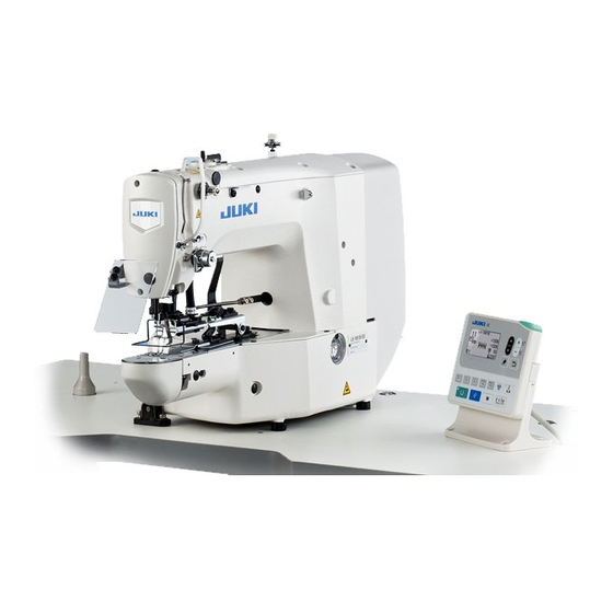
Computer-controlled high-speed bartacking machine
Hide thumbs
Also See for LK-1900B Series:
- Instruction manual (110 pages) ,
- Installing (2 pages) ,
- Specifications (7 pages)
Table of Contents


Need help?
Do you have a question about the LK-1900B Series and is the answer not in the manual?
Questions and answers