Gaggenau VL051-107 Repair Instruction
Hide thumbs
Also See for VL051-107:
- Operating and assembly instructions manual (15 pages) ,
- Operation and assembly instructions (11 pages)
Table of Contents
Advertisement
1
SAFETY ........................................................ 2
1.1
Safety instructions.............................................................. 2
1.2
Repair instructions ............................................................. 2
2
INSTALLATION ............................................ 3
2.1
Installation dimensions ...................................................... 3
2.2
Installation position 1 ......................................................... 5
2.3
Installation position 2 ......................................................... 6
2.4
Installation position 3 ......................................................... 7
3
OPERATION ................................................. 8
3.1
Features ............................................................................... 8
3.2
Display ................................................................................. 8
3.3
Switching on the appliance................................................ 9
3.4
Switching off the appliance................................................ 9
3.5
Run-on ................................................................................. 9
3.6
Vacation lock....................................................................... 9
4
COMPONENTS........................................... 10
4.1
Equipment configuration.................................................. 10
4.2
Electronics module ........................................................... 10
4.3
Current and power table with GB 031-107 ...................... 11
4.4
Lifting motor...................................................................... 11
4.5
Spare part - Pipe socket ................................................... 12
5
FUNCTIONS ............................................... 13
6
REPAIR....................................................... 13
142_58300000122107_ara_en_b.doc - 02.02.09
R
E
P
A
I
R
I
N
S
T
R
U
C
T
I
O
N
R
E
P
A
I
R
I
N
S
T
R
U
C
T
I
O
N
R
E
P
A
I
R
I
N
S
T
R
U
C
T
I
O
N
VL051
7
FAULT DIAGNOSTICS ...............................14
7.1
Switch logic S1-S4............................................................ 14
7.2
Plastic hose is twisting .................................................... 15
7.3
Too little air power............................................................ 15
8
TECHNICAL SPECIFICATIONS.................16
8.1
Performance characteristic VL 051 with GB 031 ........... 16
Seite 1 von 16
Advertisement
Table of Contents

Related Manuals for Gaggenau VL051-107


Summary of Contents for Gaggenau VL051-107
-
Page 1: Table Of Contents
VL051 SAFETY ............2 FAULT DIAGNOSTICS .......14 Safety instructions.............. 2 Switch logic S1-S4............14 Repair instructions ............. 2 Plastic hose is twisting ............ 15 Too little air power............15 INSTALLATION ..........3 TECHNICAL SPECIFICATIONS....16 Installation dimensions ............3 Installation position 1 ............5 Performance characteristic VL 051 with GB 031 ... -
Page 2: Safety
SAFETY Repair instructions To prevent unnecessary repair costs, observe the following repair Safety instructions instructions: ► NEVER attempt repairs by randomly replacing components! ► Always proceed systematically and observe the trouble- Warning of dangerous electrical voltage! shooting instructions in the technical documentation. ►... -
Page 3: Installation
INSTALLATION Installation dimensions Note A wok, e.g. VG 231, must not be installed next to the VL 051. If operated next to a gas appliance, the swivel arm must be extended at least as far as the upper edge of the pan. If installed next to a gas appliance, e.g. - Page 4 2.1.1 Installing retaining clamp 142_58300000122107_ara_en_b.doc – 02.02.09 Seite 4 von 16...
-
Page 5: Installation Position 1
Installation position 1 142_58300000122107_ara_en_b.doc – 02.02.09 Seite 5 von 16... -
Page 6: Installation Position 2
Installation position 2 142_58300000122107_ara_en_b.doc – 02.02.09 Seite 6 von 16... -
Page 7: Installation Position 3
Installation position 3 142_58300000122107_ara_en_b.doc – 02.02.09 Seite 7 von 16... -
Page 8: Operation
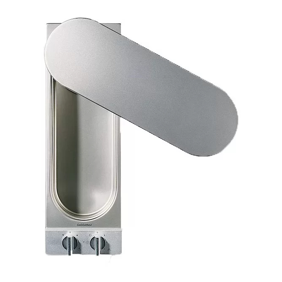
OPERATION Display Features Fig. 3 Control knob for height setting Filter indicator light Control knob for power setting Fig. 2 Grease filter Cover Swivel arm Trough Fascia 142_58300000122107_ara_en_b.doc – 02.02.09 Seite 8 von 16... -
Page 9: Switching On The Appliance
Switching on the appliance Switching off the appliance Fig. 4 Fig. 5 Rotate power setting control knob to the required setting. The swivel arm moves automatically into the roasting position. Rotate power setting to Pos. 0. The swivel arm can be set to any height with the height- Rotate height adjustment to left to “retract”... -
Page 10: Components
COMPONENTS Electronics module Equipment configuration Microswitch connector Pos. A grill position, lower end Microswitch connector Pos. B crush protection, upper end Fan motor connector Pos. C Lifting motor connector Pos. D Electronics module Pos. A Capacitor 12 µF Pos. B Lifting motor Pos. -
Page 11: Current And Power Table With Gb 031-107
Lifting motor At the outputs L1, L2 for the blower only 0 or 230V can be measured against N. The individual speeds are generated by upstream capacitors and resistors. See table Output L1 Output L2 Circuit Off and pipe retracted Basic setting 12 µF + 8 µF 230 V... -
Page 12: Spare Part - Pipe Socket
Spare part - Pipe socket The spare part pipe socket is supplied as individual part… … and must be separated before the assembly. 142_58300000122107_ara_en_b.doc – 02.02.09 Seite 12 von 16... -
Page 13: Functions
FUNCTIONS REPAIR There are no error messages 142_58300000122107_ara_en_b.doc – 02.02.09 Seite 13 von 16... -
Page 14: Fault Diagnostics
FAULT DIAGNOSTICS Lifting motor and fan lower grill upper crush Switch logic S1-S4 output position protection Lifting motor runs to upper end Lifting motor and fan motor do not run Basic setting is running, Fan can be switched to any setting Lifting motor does not Lifting motor and fan motor do not run... -
Page 15: Plastic Hose Is Twisting
Plastic hose is twisting Too little air power Complaint: Extraction is too weak or the fumes go past the extraction arm. Cause: Units VL 051 and GB 031 have a free-blowing air power of 350 m³/h. (See performance characteristic) Additional pipelines reduce the power further. Flat ducts are unsatisfactory as regards air flow and should not be used. -
Page 16: Technical Specifications
TECHNICAL SPECIFICATIONS Type Voltage Frequency Power maximum VL051-107 220–240 V 50 Hz 280 W Performance characteristic VL 051 with GB 031 VL 051-107 with GB 031-107 Setting 0 Setting 1 Setting 2 Setting 3 Volumetric flow in m³/h 142_58300000122107_ara_en_b.doc – 02.02.09...
Need help?
Do you have a question about the VL051-107 and is the answer not in the manual?
Questions and answers