powersoft Duecanali 804 Service Manual
Hide thumbs
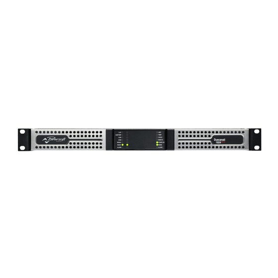
Also See for Duecanali 804:
- Quick manual (43 pages) ,
- User manual (42 pages) ,
- User manual (45 pages)
Table of Contents
Advertisement
Duecanali / Quattrocanali Series
Duecanali 804
Duecanali 1604
Duecanali 4804
Quattrocanali 1204
Quattrocanali 2404
Quattrocanali 4804
©2017 Powersoft
powersoft_Quattrocanali_servman_en_v2.8
Duecanali 804 DSP+D
Duecanali 1604 DSP+D
Duecanali 4804 DSP+D
Quattrocanali 1204 DSP+D
Quattrocanali 2404 DSP+D
Quattrocanali 4804 DSP+D
Service Manual
Keep this manual
for future reference
Advertisement
Table of Contents

Related Manuals for powersoft Duecanali 804


Summary of Contents for powersoft Duecanali 804
- Page 1 Duecanali / Quattrocanali Series Duecanali 804 Duecanali 804 DSP+D Duecanali 1604 Duecanali 1604 DSP+D Duecanali 4804 Duecanali 4804 DSP+D Quattrocanali 1204 Quattrocanali 1204 DSP+D Quattrocanali 2404 Quattrocanali 2404 DSP+D Quattrocanali 4804 Quattrocanali 4804 DSP+D Service Manual ©2017 Powersoft Keep this manual powersoft_Quattrocanali_servman_en_v2.8...
- Page 2 Intentionally left blank...
- Page 3 QUATTROCANALI | SERVICE MANUAL Quattrocanali Service Manual Structure Safety Information Index Equipment Requirement Service Precautions Notes on Soldering Notes on Replacing Parts Serial NumberLabels Mac Address Labels Description of The Amplifer Parts External 5.1.1 Replacing the Filters 5.1.2 Quattrocanali Front Panel Introduction 5.1.3 Duecanali Front Panel Introduction 5.1.4...
- Page 4 QUATTROCANALI | SERVICE MANUAL 10.4.1 What is Failsafe Mode? 10.4.2 How do I tell if a device is in FailSafe Mode? 10.4.3 How do I Recover from Failsafe Mode? 10.5 Using Failsafe Recovery 10.6 Dante Dynamic IP Restore Testing the Unit via ArmonìaPlus 1.3 4CH / 2CH Platform DSP Rescue Procedure Updating of the Firmware using...
- Page 5 QUATTROCANALI | SERVICE MANUAL Troubleshooting Structure SYMPTOM AREA SYMPTOM POSSIBLE CAUSES CHECK ACTIONS DSP+D / Control Board AUDIO No Audio Check Internal LEDs Swap Golden Sample DSP+D / Control Board ArmonìaPlus Update Firmware Flat Cables Check any damaged Swap Golden Sample Main Board Check Internal LEDs Swap Main Board...
- Page 6 The components to be replaced are clearly shown to help their Normal Operating Conditions identification. At the end of this guide you can find a detailed Checking the Fan list with the description and the respective Powersoft internal Front Panel Fault Indications reference code of the spare parts. Global Faults Always use an anti-static wrist band while servicing the amplifier.
-
Page 7: Service Precautions
4.2 Notes on REPLACING PARTS About the AMP Module The amplifier module of this unit is able to correspond to repairing in the component manufacturer (Powersoft Company). And it holds charge-free warranty period for 16 months after production. 4.3 Serial Number Labels The details of the Serial Number Labels is as follows. -
Page 8: Replacing The Filters
QUATTROCANALI | SERVICE MANUAL 5. Description of The Amplifer Parts 5.1 External 5.1.1 Replacing the Filters The left side and right side panels can be extracted by simply pulling on them, releasing them from the magnet which holds them in place. - Page 9 QUATTROCANALI | SERVICE MANUAL 5.1.3 Duecanali Front Panel Introduction Control Panal LED Panel Operating Mode LEDs (ON/STANDBY) Channel Status LED meters Power pushbutton System Status LEDs Armonía Callback pushbutton Serial Port HSoft Reset pushbutton Reserved for Service Operstions Hard Reset pushbutton Self Check pushbutton CH1, CH2 attenuators 5.1.4 Basic Amplifier Operation...
-
Page 10: System Status Leds
QUATTROCANALI | SERVICE MANUAL 5.1.5 Display LED Configurations and Further References Channel Bars LEDs Colour Signal metering Clipping ORANGE *DSP+D User Limiter YELLOW -6dB GREEN -12dB GREEN -24dB GREEN -60dB GREEN 1 Red LED lights on in case of any kind of channel fault that prevents the normal channel operating; at the same time the rear corresponding GPO toggles the contacts NO into NC and NC into NO. - Page 11 QUATTROCANALI | SERVICE MANUAL 5.1.6 Quattrocanali Rear Panel Introduction AC Mains Connector Alarm Connector Air Vent Dante™ Port (DSP+D version only) Output Connector Ethernet Port Line input Connector System Configuration Dip Switches CH1, CH2 Output Configuration Dip Switches Remote Levels Connector CH3, CH4 Output Configuration Dip Switches Remote On/Off 5.1.7 Duecanali Rear Panel Introduction...
-
Page 12: Front Panel Board
QUATTROCANALI | SERVICE MANUAL 5.2 Internal 5.2.1 Main Module Locations Layout Type of Rear Board Colour Description DSP+D / CNTRL Board Fan + Fan’s Duct Quattrocanali (4CH) Main Board Rear Board Front Board Duecanali (2CH) EPROM: Front Panel Board Amplifier’s Model Amplifier’s Serial Number Amplifer’s MAC Address EPROM... -
Page 13: Mainboard Layout
QUATTROCANALI | SERVICE MANUAL 5.2.2 Main Board Layout Layout Old Versions New Versions Colour Description CH4 Power Amp CH3 Power Amp CH2 Power Amp CH1 Power Amp Output Cable + Bulk Capacitors & Zobel Resistors Network PFC Converter Colour Description EMI Filter + Fuses Fuse A PSU Control Section... - Page 14 QUATTROCANALI | SERVICE MANUAL 5.2.3 Main Board MOSFETs & Diodes Layout PFC 2 CH 4 Diodes MOSFETs PFC 2 CH 3 MOSFETs MOSFETs CH 2 PFC 1 MOSFETs MOSFETs CH 1 MOSFETs PFC 1 Diodes...
-
Page 15: Control Board Layout
QUATTROCANALI | SERVICE MANUAL 5.2.4 DSP+DANTE Board Layout DSP+D Board (Old Version) DSP+D Board (New Version) Layout Colour Description Audio Control Section DANTE Section DANTE ETH Port DSP ETH Port 5.2.5 CONTROL Board Layout Layout Colour Description Audio Control Section DSP Processor DSP ETH Port... -
Page 16: Front Board Layout
QUATTROCANALI | SERVICE MANUAL 5.2.6 Rear Board Layout Quattrocanali (4CH) Duecanali (2CH) Layout Colour Description Load Setting Switches Audio Input Connectors Remote Level Connectors Alarm Connectors 5.2.7 Front Board Layout Quattrocanali (4CH) Duecanali (2CH) Layout Colour Description CH Level Potentiometers LEDs Panel... - Page 17 QUATTROCANALI | SERVICE MANUAL 5.3 Phoenix Connectors Connection Informations INPUT OUTPUT (Single-Ended) Phoenix MC 1,5/12-ST-3,81 1803675 Phoenix PC 5/ 8-STF1-7,62 1777891 GPO / ALARM OUTPUT (Bridged) Phoenix MC 1,5/12-ST-3,81 1803675 Phoenix PC 5/ 8-STF1-7,62 1777891 REMOTE LEVEL INPUT (Link Channel Pairs)* Phoenix MC 1,5/12-ST-3,81 1803675 Phoenix MC 1,5/12-ST-3,81 1803675 REMOTE ON | REMOTE OFF...
-
Page 18: Disassembling Procedure
QUATTROCANALI | SERVICE MANUAL 6. Disassembling Procedure 6.1 Removing the Amplifier’s Cover The Quattrocanali & Duecanali feature a cleverly engineered Untighten the screws by 3 complete turns, 2 on each side. opening mechanism, there is no need to remove the screws completely in order to open the amplifier’s cover. - Page 19 QUATTROCANALI | SERVICE MANUAL 6.2 Disassembling the Fan Unclip the fan’s duct by gently unclipping the retainer indicated in the portrayed picture. Lift and remove the fan’s duct. Unplug the fan’s connector. Note that the 2 screws highlighted in the following picture (yellow) sould not be present nor inserted.
- Page 20 QUATTROCANALI | SERVICE MANUAL 6.3 Main Board Disassembling Unplug the mains’ Faston connectors. Unclip the safety retainer from the ground connector Proceed by removing all the flat cables connecting the Main Board to the DSP+D/CNTRL and Front boards. Also from the Rear Board to the DSP+D/CNTRL Board. Older versions of the Quattrocanali feature the flat cables tucked in between the boards.
- Page 21 QUATTROCANALI | SERVICE MANUAL Focus your attention on the Output’s Fastons. Note that there are currently 2 versions of the main board’s wiring, these are easily recognizable by the color coding of the output terminations. Refer to the following diagrams when reassembling the amplifier.
- Page 22 QUATTROCANALI | SERVICE MANUAL Gently remove the Eprom (purple) and place in the new Main Board With a T10 Torx screwdriver, remove the 8 screws highlighted (yellow) in the picture below. It is now possible to extract the Main Board from the chassis, please do so by gently pivoting it towards the front of the amplifier by pulling upwards and outwards on the heatsink.
- Page 23 QUATTROCANALI | SERVICE MANUAL 6.4 Disassembling the DSP+D/CONTROL Board Gently remove all the flat cables connectors highlighted in yellow as indicated. Unscrew the 2 screws marked in red. 5 retention pins are located on the points highlighted in light blue. Gently push the DSP+D Board towards the front of the amplifier, releasing it from all retention pins.
- Page 24 QUATTROCANALI | SERVICE MANUAL 6.5 Front Board Disassembling By means of a T10 Torx screwdriver, remove the 2 screws holding the front panel assembly to the rack ears, one on each side. By means of a T10 Torx screwdriver, remove the 4 Torx screws highlighted in the portrayed picture.
- Page 25 QUATTROCANALI | SERVICE MANUAL Unplug the Outputs’ connector Fastons. By means of a T10 Torx screwdriver, remove the 2 screws holding the rear panel assembly to the rack ears, one on each side. By means of a T10 Torx screwdriver, remove the 5 Torx screws highlighted in the portrayed picture.
-
Page 26: Troubleshooting
QUATTROCANALI | SERVICE MANUAL 7. Troubleshooting 7.1 Testing the Amplifier with DC Power Connect the Amplifier to an external DC Power Supply. Slowly increase the voltage to 60Vdc. Check if the Absorption is within the limits 450mA (±10%) @ 60Vdc Check the front panel LEDs for normal operation. - Page 27 QUATTROCANALI | SERVICE MANUAL 7.3 Internal LEDs Checks - Main Board - AMP Section - Normal Operating Conditions NOTE: If any of the Channel “ENA” LED was Blinking “GREEN”, Colour Status Action Refer to Troubleshooting Standby LED Error Code Table (Page 36) None GREEN...
- Page 28 QUATTROCANALI | SERVICE MANUAL CH3 / CH4 Fuses Colour Status Action None None Check Standby LED Troubleshooting table - Points 7 CH1 / CH2 Fuses Colour Status Action None None Check Standby LED Troubleshooting table - Points 7...
- Page 29 QUATTROCANALI | SERVICE MANUAL 7.4 Internal LEDs Checks - DSP+D Board - Normal Operating Conditions Make sure that the plug is correctly inserted in the ETH Port. Colour Status Action Colour Status Action None ORANGE BLINKING None None BLINKING None GREEN GREEN None...
-
Page 30: Checking The Fan
QUATTROCANALI | SERVICE MANUAL 7.5 Checking the Fan Remove the FAN’s connector as portrayed. With a multimeter, check the R361 Resistor. R361: 0.12 Ω Connect the fan to a DC power supply, and check its consumption as portrayed on the picture. 140 mA (±... -
Page 31: Global Faults
QUATTROCANALI | SERVICE MANUAL 8. Front Panel Fault Indicators 8.1 Global Faults Power supply fault AC Mains voltage out of range (over/under voltage) PSU temperature out of range Fan Error 8.2 Channel Faults Channel# Output Waveform non-conformity Channel# Temperature out of range Channel# Output current measurement non-conformity Check the “Troubleshooting LED Error”... -
Page 32: Self Check
QUATTROCANALI | SERVICE MANUAL 8.3 Self Check In order to perform a self check, press and hold the “Check” button, highlighted beside, for 3 seconds. The self check will not be performed if the amp is in one of these 3 conditions: Amp is off Amp is in Energy Save Mode The standby LED is on, or flashing. - Page 33 Reset Procedure and set Mains Current Internal LEDs Internal LEDs Contact the Rear switch status on Limiter Enable - Power AMP - DSP+D Powersoft OFF condition Section Board Section LIMIT Orange Check the front panel Check Power draw filters and front grid...
- Page 34 Check Replace -6dB / and Insert Contact Yellow Warning air filters and Perform the Fan Control or TEMP flat cables Powersoft or Protection Reset Procedure Consumption DSP+D Board properly Channel Out Check Check Reset Procedure and Current Test Internal LEDs...
- Page 35 Upgrade Check filters and Perform Reset and Insert Contact LIMIT Orange Fan Error the Fan’s Procedure to Repeat flat cables Powersoft consumption Self-Test properly Remove and clean air Upgrade Power Supply Check filters and Perform Reset and Insert Contact TEMP...
- Page 36 Contact Internal LEDs - and insert Internal LEDs Contact STANDBY Orange Good Signal at Service Centre Power Supply flat cables - DSP+D Powersoft Power On Section properly Board Section Failed Check Upgrade Communication Switch OFF/ Contact Internal LEDs - and insert...
-
Page 37: Dante Controller
Measure the Replace Contact STANDBY Orange properly and too Low Limit Service Centre Power AMP Railbus Fuses Main Board Powersoft check Mains Section Fuses Power Supply Check Remove the Over Remove and clean Replace Internal LEDs - Fan and to... - Page 38 QUATTROCANALI | SERVICE MANUAL Updating Dante Controller Dante Controller can be updated directly from the application itself. Checking for Updates Manually In Windows: From the Help menu, select ‘Check for Updates’. In Mac OS X / macOS: From the Dante Controller application menu, select ‘Check for Updates’. Checking for Updates Automatically Dante Controller can also check for updates automatically.
- Page 39 QUATTROCANALI | SERVICE MANUAL About Product and Dante Versions Product Version The Product Version is set by the manufacturer, and is typically used to identify the overall firmware version for the host device (which may incorporate non-Dante firmware or software). •...
- Page 40 QUATTROCANALI | SERVICE MANUAL 10.5 Using Failsafe Recovery Basic Steps To recover Dante devices in safe mode: 1. Ensure the computer running Dante Firmware Update Manager and the device you wish to recover are on the same IP subnet. (follow instruction n chapter 11.6 from point 1 to 13) 2.
- Page 41 QUATTROCANALI | SERVICE MANUAL Screen 2- Finding devices for safe recovery This screen indicates that Firmware Update Manager has detected at least device in safe mode, and is scanning the network for the full list. It should take less than a minute to find all applicable devices. When you are sure that all your safe mode devices have been found, click Stop Scan.
- Page 42 QUATTROCANALI | SERVICE MANUAL 10.6 Dante Dynamic IP Restore 1. Download the last version of Dante controller (or at least 4.06.xx version) and install it on your PC (the download is available on https://www.audinate.com/products/software/dante-controller) 2. Execute Dante Controller on your PC 3.
- Page 43 QUATTROCANALI | SERVICE MANUAL 5. Take note about the IP address set on the device (ex. 169.254.200.121) 6. Close Dante controller 7. On your PC enter Control Panel. 8. Open “Network and sharing center” 9. Click on “Change adapter setting” 10.
- Page 44 QUATTROCANALI | SERVICE MANUAL 12. Select TCP/IPv4 and click on properties. The following windows will be shown 13. Take note of your original configuration and then configure your computer’s network interface with a static IP address in the same range as the IP address for the Dante device. Use the same values for the first three octets and choose a different number from 1 to 255 for the last octet (in this example Dante IP address is 169.254.200.121 , then choose 169.254.200.1 for your PC IP address).
- Page 45 QUATTROCANALI | SERVICE MANUAL 11. Testing the Unit via ArmonìaPlus 1.3 Connect the unit to a PC via the Ethernet slots GREEN led ON (flashing) Link/Activity indicator: Blinking – There is activity on this port. Off – No link is established GREEN led ON (solid) Connection is correctly established between the two devices YELLOW led ON ETH speed connection...
- Page 46 QUATTROCANALI | SERVICE MANUAL The Unit and its Serial Number should appear within 5 seconds By hover the mouse cursor on top of the unit’s icon, it is possible to check the Model, Serial, Retel(IP Address), Firmware Apply a 1KHz 1Vpp audio signal to CH1 Check for presence of the signal in all the other channel’s VMeters Drag and drop the unit into the Workshop, notice the ‘white/red Function...
- Page 47 QUATTROCANALI | SERVICE MANUAL 12. 4CH / 2CH Platform DSP Rescue Procedure 1. Connect the PC to the amplifier via ETH port 192.168.5.100. 2. Set the PC IP address as The subnet mask will be automatically set. upgrade4-v1.7.6.74.zip 3. Copy the file “ ”...
- Page 48 QUATTROCANALI | SERVICE MANUAL 8. Release all push buttons. After a few seconds all front leds may turn OFF and after few seconds only few turn ON 9. Check the ETH green led port is blinking 10. Wait 20 sec. and then launch the browser on your PC 192.168.5.200 11.
- Page 49 QUATTROCANALI | SERVICE MANUAL 14. Select “Upload” from the following screen: 15. The procedure will take approx. 10 min. During running procedure the leds condition will change randomly. After some minute the front leds MAIN, POWER ON and READY must be ON 16.
- Page 50 QUATTROCANALI | SERVICE MANUAL 13. Updating of the Firmware using ArmonìaPlus 1.3 On the bottom of the Armonia Workspace panel, click on “Match” & on the top panel, click on “Discovery” in order to load the unit. This procedure may take up to 5 seconds. Once properly loaded, the Amplifier and its Serial Number should appear on the window.
- Page 51 QUATTROCANALI | SERVICE MANUAL 14. Updating of the Firmware using Dante Controller Connect the unit to a PC via the Dante slots. Launch Dante Controller Application. Click on the “Icon” to Update Dante Firmware. Or open View Tap to Launch Dante Updater Application. Click on the “Box”...
- Page 52 QUATTROCANALI | SERVICE MANUAL 15. Quattrocanali & Duecanali Series Hardware Composition Part Number Product Code Main Ctrl Front Rear QUATTROCANALI No DSP No Dante 4804 PF000465 SMD01094.R SM001101.R SM001097.R SM001099.R 2404 PF000464 SMD01095.R SM001101.R SM001097.R SM001099.R 1204 PF000463 SMD01095.R SM001101.R SM001097.R SM001099.R Product Code...
-
Page 53: Replacement Parts
QUATTROCANALI | SERVICE MANUAL 17. Replacement Parts PART NUMBER DESCRIPTIONS 4CH/STD/MAIN + DISS FOR REPAIR SMD01094.R (QUATTROCANALI 4808 MAIN BOARD) 4CH/LGT/MAIN + DISS FOR REPAIR SMD01095.R (QUATTROCANALI 2404 & 1204 MAIN BOARD) 2CH/STD/MAIN + DISS FOR REPAIR SMD01096.R (DUECANALI 1604 & 804 MAIN BOARD) 2CH/HGT/MAIN + DISS FOR REPAIR... - Page 54 QUATTROCANALI | SERVICE MANUAL 4CH/STD/REAR FOR REPAIR SM001099.R (QUATTROCANALI REAR BOARD) SM001100.R 2CH/STD/REAR FOR REPAIR (DUECANALI FRONT BOARD) 4CH/STD/CNTRL FOR SM001101.R REPAIR (CONTROL BOARD) SM001107.R 4CH/STD/DSP FOR REPAIR (DSP BOARD) VN000040.R BLOWER 120X120X32 _12V_1.12A FOR REPAIR ME001151.00 4CH - Fan duct GU000096.02 AIR BOX GASKET - F.CABLE BLOCK...
- Page 55 FI000030.00 4CH - FILTER FRONT PANEL MAT. POLIESTIC 10 PP FI000032.00 4CH - FILTER HEATSINK ET000132.00 2/4/8 CH FRONT LABEL POWERSOFT LOGO ET000589.00 2CH 1604 - FRONT LABEL ET000590.00 2CH 1604 DSP + DANTE FRONT LABEL ET000591.00 4CH 2404 - FRONT LABEL ET000592.00...
- Page 56 QUATTROCANALI | SERVICE MANUAL KT000908.R 4CH KIT EXTERNAL CONNECTORS KT000907.R 2CH KIT EXTERNAL CONNECTORS 8P_S.ROW PLUG 180° PNL CN000485 H14.3mm Pitch=7.62mm Solder/S IEC20A mains inlet socket CN000646 0722-1-PW25-CBK 0722-1 series CB000667.00 Cabl.4CH ground connection SCW|TCBTX|M3X6_ VI000393 T10_|SPEC_PWT GLSTL_|4.8_|WHR_DIN127B VI000377 SCW TCTX M5X12 VI000276.01 SPC | M3X5 | MF | RND | BRASS_80PPM |N|...
- Page 57 QUATTROCANALI | SERVICE MANUAL FU000026 FUSE 10A 250VDC T/LAG (5x20mm) FU000038 FUSE CARTRIDGE 15A (6x32mm) 3AB Slo-Blo FUSE CARTRIDGE 10A FU000039 (6x32mm) 3AB Slo-Blo 325/326 Series FU000060 2A_|W4.2D8.6H8.4|SLW|250V PCB|_|RST_|LT23.0_|L|_ VR000007 VARISTOR S20K385 CB000665.00 FLAT CABLE 20P L 45mm CB000666.00 4CH 34P INTERNAL CONNECTION MAINS CABLE 3x1,5 CV000061...
- Page 58 QUATTROCANALI | SERVICE MANUAL 18. Location to Paste the Anti-Tamper Label after Repaired. For every In-Warranty repair, you have to paste the Anti-Tamper Label on the instructed position. Upon receiving the Faulty Unit, inspect the Label to see if there’s any Tampering.
-
Page 59: Waveform Chart
QUATTROCANALI | SERVICE MANUAL 19. Waveform Chart Main Mains Reference Amp. Input Reference Models Board Part Voltage Load PCB Layout Connection Probe PCB Layout Waveform Name Condition Signal Test Point Number Applied Waveform QUATTRO -CANALI SMD01094.R 4804 100V Standby None None U301 pin 6 TEK00001... - Page 60 QUATTROCANALI | SERVICE MANUAL U1 pin 4 QUATTRO (192KHz 4804 SMD01094.R 100- None None master TEK00013 2404 SMD01095.R 240V clock Grounded on amplifier 1204 CH1-2) chassis U1 pin 10 QUATTRO (192KHz 4804 SMD01094.R 100- None None master TEK00014 2404 SMD01095.R 240V clock Grounded on amplifier...
- Page 61 Customer_Service_APAC / Customer_Service_CALA for the VOID_OEM Folder 3. Provide Serial Number & Model of the VOID Bias Q2/ Q1/D1 to allow Powersoft HQ to customize the Installer Program (“devList.xml”) Note: The Powersoft Service Team will provide this “devList.xml” customized for that Specific VOID Model Amp.
- Page 62 QUATTROCANALI | SERVICE MANUAL 14. The following screen will be shown: 15. Click on “Choose File” and select the file “upgrade4.zip” from you PC 16. Select “Upload” from the following screen: 17. The “Uploading & Installing” procedure will take approx. 10 min. During running procedure the LEDs condition will change randomly.
- Page 63 QUATTROCANALI | SERVICE MANUAL 21. Launch ArmoniaPlus to Update the Firmware 22. Select the Amp & Click “UPDATE” 23. Click “UPDATE” to begin 24. Uploading in progress 25. Installing in progress 26. Firmware Update completed 27. Note the IP Address of the Amplifier 169.254.xxx.xxx...
- Page 64 QUATTROCANALI | SERVICE MANUAL 28. Open the “VOID_OEM” Folder, Paste the “devList.xml” Files inside the Folder 29. Launch the “VOID_OEM” Program 30. Fill the IP Address Field 169.254.xxx.xxx and then Press “Connect” 31. The software will configure the amplifier as “VOID” then it will send automatically a “Factory Default”...
- Page 65 QUATTROCANALI | SERVICE MANUAL 35. Click on “Browse” and select the file “upgrade4-void.zip” from you PC 36. Select “Upload” from the following screen: 37. The “Uploading & Installing” procedure will take approx. 10 min. During running procedure the LEDs condition will change randomly After some minute the Front Panel LEDs, POWER ON and READY must be ON...
-
Page 66: Safety Precautions
QUATTROCANALI | SERVICE MANUAL IMPORTANT SAFETY ADDENDUM The aim of this addendum is to describe the safety precautions to be undertaken when servicing any Powersoft amplifier/module. WE RECOMMEND THAT ALL SERVICE OPERATIONS ARE CARRIED OUT BY A TRAINED TECHNICIAN IF NOT EXPLICITLY STATED OTHERWISE, DISCONNECT THE AMPLIFIER FROM THE MAINS. - Page 67 Intentionally left blank...
- Page 68 Tel: +39 055 735 0230 Fax: +39 055 735 6235 General inquiries: info@powersoft.it Sales: sales@powersoft.it Application & technical support: support@powersoft.it Service & maintenance: service@powersoft.it powersoft-audio.com Data are subject to change without notice. For latest update please refer to the online version available on www.powersoft-audio.com...
Need help?
Do you have a question about the Duecanali 804 and is the answer not in the manual?
Questions and answers