Table of Contents
Advertisement
Quick Links
TLE5501 Eval Kit
Scope and purpose
This document describes the Evaluation Kit for the TLE5501 TMR based angle sensor.
The purpose of this manual is to describe the software installation process and how to use the TLE5501 angle
sensor Evaluation Kit.
Intended audience
This document is intended for anyone who wants to use the TLE5501 Evaluation Kit
1
Rev. 1.0
www.infineon.com
2018-08-01
Advertisement
Table of Contents

Subscribe to Our Youtube Channel
Summary of Contents for Infineon TLE5501
- Page 1 Scope and purpose This document describes the Evaluation Kit for the TLE5501 TMR based angle sensor. The purpose of this manual is to describe the software installation process and how to use the TLE5501 angle sensor Evaluation Kit. Intended audience This document is intended for anyone who wants to use the TLE5501 Evaluation Kit Rev.
-
Page 2: Table Of Contents
TLE5501 Eval Kit Table of contents Table of contents ............... . . 2 General description . -
Page 3: General Description
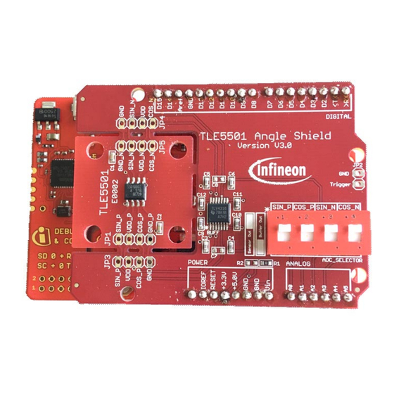
Infineon XMC1100 Boot Kit Figure 2 TLE5501 Angle Shield The Eval Kit is complemented by the TLE5501 Eval Kit GUI (Evaluation Kit for Angle Sensors window, see Figure For connection to the PC a micro USB cable is required. Notes 1. - Page 4 General description TLE5501 Angle Shield description The TLE5501 Angle Shield has to be plugged onto the Boot Kit. Care has to be taken that the pins are correctly aligned. The TLE5501 sensor is soldered on the shield in a “breakout” area that can be easily broken of the shield and used in another application if needed.
-
Page 5: Installation
2. Install the programmer software by double-clicking on the file: TLE5501_EvalKit_vx.msi. 3. If you do not have installed Segger Driver & .NET 3.5 included with this installer, install them. 4. Start the installed software TLE5501 – Eval Kit. Rev. 1.0... -
Page 6: Evaluation Kit For Angle Sensors
After starting the software, a device should appear in the Programmer list, click the Connect button to connect the Eval Kit. In the Sensor drop-down list select the sensor TLE5501 and click Start. The Evaluation Kit for Angle Sensors window shows the real time angle read-out... -
Page 7: Sensor Readout
TLE5501 Eval Kit Evaluation Kit for Angle Sensors Sensor readout The Evaluation Kit for Angle Sensors window displays the uncalibrated differential angle with the angle gauge. It also reports the voltage for each output (SinP, CosP, SinN, CosN). Figure 3 Evaluation Kit for Angle Sensors window Rev. -
Page 8: How To Calibrate
TLE5501 Eval Kit Evaluation Kit for Angle Sensors How to calibrate For analog angle sensors, the offset, amplitude and orthogonality of the raw signals sin and cos has to be calibrated to achive high angl eaccuracy. This calibration procedure can be performed as described below: Click Calibrate. -
Page 9: Safety Features
• The right-down area of the Evaluation Kit for Angle Sensors window displays information that is related to the safety concept for TLE5501 described in the Product Safety Manual. • To get all the safety fields populated a calibration is required. -
Page 10: Output Buffer
TLE5501 Eval Kit Evaluation Kit for Angle Sensors Output buffer On the sensor shield, there are 4 DIP switches which allow to select an output buffer for the analog raw signal sin and cos. With this buffer enabled, a low output impedance is provided. -
Page 11: Revision History
TLE5501 Eval Kit Revision history Revision history Revision Date Changes Rev. 1.0 2018-08-01 Initial creation. Rev. 1.0 2018-08-01... - Page 12 Infineon Technologies, customer's products and any use of the product of Infineon Technologies’ products may not be used in Infineon Technologies in customer's applications. any applications where a failure of the product or any...


Need help?
Do you have a question about the TLE5501 and is the answer not in the manual?
Questions and answers