Table of Contents
Advertisement
Quick Links
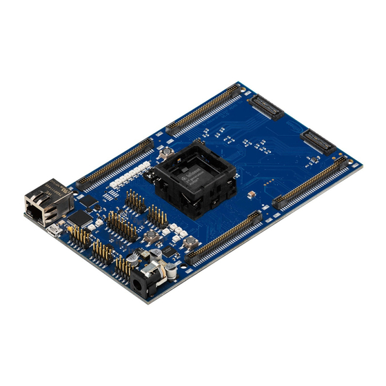
TriBoard TC3X7
TriBoard Manual TC3X7
Hardware: TriBoard TC3X7 TH V2.0( 1) and TriBoard TC3X7 V2.0
About this document
Scope and purpose
The User Manual provide information about using, configuration and connecting the TriBoard with Infineon
AURIX™ TC3X7 device. The manual provide information for different hardware types. There exist different
hardware with Through Hole socket (TriBoard TC3X7 TH) and soldered devices (TriBoard TC3X7). The schematic
is identically for the all boards if not other mentioned in chapter schematic. The placing on the boards is slightly
different around the TC3X7 itself dependent of the space (socket need more space and has through hole), but the
most components are on the same location. All figures are valid for each board if not differently mentioned.
Intended audience
Design, verfication, test and software engineers will use this document to get an understanding of the
functionality and connections of the TriBoard.
User Manual
www.infineon.com
Please read the Important Notice and Warnings at the end of this document
TriBoard TC3X7 TH V2.0(1) and TriBoard TC3X7 V2.0
V2.3
2019-09
Advertisement
Table of Contents

Related Manuals for Infineon TriBoard AURIX TC377


Summarization of Contents
About this document
Scope and Purpose
Outlines the manual's aim: information on using, configuring, and connecting the TriBoard.
Intended Audience
Identifies the target readers: design, verification, test, and software engineers.
Features
Summary of Features
Lists key features of the TriBoard, including controller, transceivers, and interfaces.
Connectors
Details the various connectors available on the TriBoard for different interfaces.
Components
Lists the key electronic components and their functions on the TriBoard.
Block Diagram
Illustrates the overall architecture and connectivity of the TriBoard.
Placement
Diagram showing the physical layout and location of components on the board.
TriBoard Information
Soldered Board
Describes the TriBoard TC3X7 V2.0, which has a soldered microcontroller.
Socketed Board
Details the TriBoard TC3X7 TH V2.0(1) with a socket for microcontroller placement.
Usable Devices
Lists the microcontroller devices compatible with the TriBoard.
Restricted Usable Devices
Lists devices with limited functionality or specific usage notes on the TriBoard.
Power Supply
Explains the power supply generation and input requirements for the TriBoard.
Failsafe Handling
Describes the failsafe mechanism and its configuration for the power supply supervisor.
LEDs
Details the onboard LEDs, their colors, and the signals they indicate.
Clock
Information about the onboard clock source and its configuration.
USB Connector
Describes the USB connector for PC connection, power, and debugging.
Serial Connection to PC
How to establish a serial communication connection via USB.
miniWiggler JDS
Details the miniWiggler JDS for device debugging via JTAG.
FlexRay™ (E-RAY)
Information on the FlexRay™ communication interface and its connectors.
Serial EEPROM
Description of the onboard serial EEPROM for node address storage.
MultiCAN
Details the MultiCAN transceivers for CAN communication on the board.
LIN
Information regarding the LIN transceiver and its master/slave modes.
Ethernet
Describes the Ethernet interface, PHY, and connector.
HSCT (optional)
Information on the HSCT interface and its optional usage.
High Speed with HSCT
Configuration for achieving high-speed HSCT communication.
ADC
Details the Analog-to-Digital Converter channels and their filter components.
Other Peripherals
Mentions availability of peripheral signals on different connectors.
Toggle LED's
Explains how status LEDs can be controlled by software.
Buttons
Describes the onboard buttons for reset and wake-up functions.
Debug System
Overview of the debug interfaces available on the TriBoard.
OCDS1
Details the OCDS1 interface for connecting a debugger.
DAP
Describes the DAP connector for connecting a Debug Access Port.
DAPE (only Emulation Device)
Information on the DAPE connector for emulation devices.
DAP_SCR
Describes the DAP_SCR connector for standby controller connection.
High Speed with DAP/DAPE
Configuration for achieving high-speed DAP/DAPE communication.
AGBT (optional)
Information on the optional AGBT interface for high-speed connection.
ETK Connector (optional)
Details the optional ETK connector for connecting to an ETK.
EmW Power (optional)
Describes the optional power connector for the Ethernet miniWiggler.
TriBoard Configuration
HW Boot Configuration
Explains the hardware configuration switches for boot mode selection.
Default Pad State
Describes the selection of default pad states using DIP switches.
Bootmode
Details the different startup modes selectable via boot configuration.
Assembly Options
Lists optional components and their assembly configurations.
General Optional Resistors
Details the purpose and location of general optional resistors.
Resistors for Peripherals
Lists resistors specific to the configuration of various peripherals.
Signal (on board used) Description
Power Signals
Lists and describes the power signals available on the TriBoard.
Reset Signals
Details the various reset signals and their functions.
Config Signals
Describes the configuration signals used for board setup.
Clock Signals
Lists and describes the clock signals for system operation.
Debug Signals
Details the signals used for debugging the microcontroller.
Peripheral Signals
Lists and describes signals related to various peripherals on the board.
Connector Pin Assignment
On Board Only Used Signals
Identifies port pins used only internally on the board.
TC397/TC387/TC377/TC3E7 Connector / Top View
Pinout details for the main microcontroller connectors.
TC367 Connector / Top View
Pinout details for the TC367 microcontroller connector.
TC337/TC327 Connector / Top View
Pinout details for the TC337/TC327 microcontroller connector.
Power Connector Pinout
Diagram showing the pin configuration of the power connector.
USB Connector Pinout
Diagram illustrating the pinout of the USB connector.
FlexRay™ (ERAY) Connector Pinout
Pinout diagram for the FlexRay™ communication connector.
CAN Connector Pinout
Pinout diagram for the CAN communication connector.
LIN Connector Pinout
Pinout diagram for the LIN communication connector.
HSCT Connector Pinout
Pinout diagram for the HSCT interface connector.
Ethernet Connector Pinout
Pinout diagram for the Ethernet RJ45 connector.
OCDS1 Connector Pinout
Pinout diagram for the OCDS1 debug connector.
DAP Connector Pinout
Pinout diagram for the Debug Access Port (DAP) connector.
ETK Connector Pinout
Pinout diagram for the optional ETK connector.
Ethernet miniWiggler Power Connector Pinout
Pinout diagram for the Ethernet miniWiggler power connector.
AGBT Connector Pinout
Pinout diagram for the optional AGBT connector.
Schematic and Layout
Known Problems
Lists any known issues or errata related to the board hardware.
Schematic
Provides the circuit schematic diagrams for the TriBoard.
Layout
Shows the physical component placement on the PCB top layer.
Layout with Dimensioning
Provides mechanical dimensions and layout guidelines for extension boards.
Need help?
Do you have a question about the TriBoard AURIX TC377 and is the answer not in the manual?
Questions and answers