Table of Contents
Advertisement
Quick Links
Advertisement
Table of Contents

Subscribe to Our Youtube Channel
Related Manuals for THORLABS ELL6


Summary of Contents for THORLABS ELL6
- Page 1 ELL6(K), ELL9(K), and ELL12(K) Optic Slider Kits Operating Manual...
-
Page 2: Table Of Contents
ELL6(K), ELL9(K), and ELL12(K) Optic Slider Kits Table of Contents Chapter 1 Introduction ......................1 Chapter 2 Safety Information ..................... 2 Chapter 3 Installation ......................4 Chapter 4 Operation ......................7 4.2.1 Hand-Held Controller ..........................8 4.2.2 Software Control ............................9 4.2.3... -
Page 3: Chapter 1 Introduction
The sliders can be post-mounted using our ER series cage system rods and a CP33(/M) Cage Plate (see Section 3.2.). They are also compatible with 30 mm cage systems. The ELL6, with its single motor, can be simultaneously controlled and powered via USB. The TPS101 5 V power supply is also compatible. As the two motors on the ELL9 and ELL12 require greater power, a 5 V power supply is included with the ELL9K and ELL12K bundles. -
Page 4: Chapter 2 Safety Information
ELL6(K), ELL9(K), and ELL12(K) Optic Slider Kits Chapter 2: Safety Information Chapter 2 Safety Information For the continuing safety of the operators of this equipment, and the protection of the equipment itself, the operator should take note of the Warnings, Cautions and Notes throughout this handbook and, where visible, on the product itself. - Page 5 ELL6(K), ELL9(K), and ELL12(K) Optic Slider Kits Chapter 2: Safety Information Caution The home sensor of the device relies on a 950nm led which can leak from the device. This should be taken into consideration for environments that are especially sensitive to foreign light sources.
-
Page 6: Chapter 3 Installation
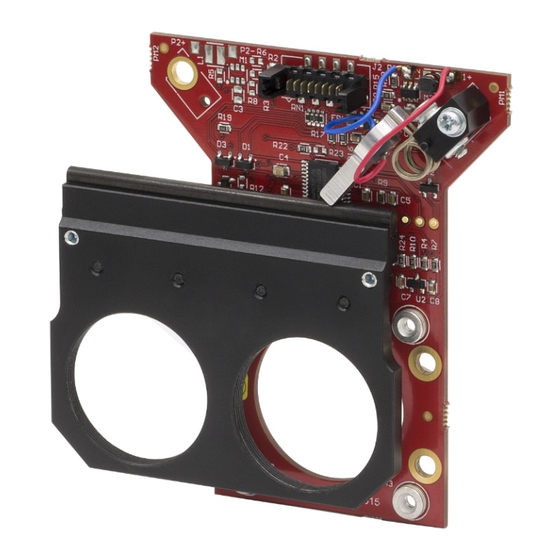
ELL6(K), ELL9(K), and ELL12(K) Optic Slider Kits Chapter 3: Installation Chapter 3 Installation Environmental Conditions Warning Operation outside the following environmental limits may adversely affect operator safety. The unit is designed for indoor use only. To ensure reliable operation, the unit should not be exposed to corrosive agents or excessive moisture, heat or dust. - Page 7 ELL6(K), ELL9(K), and ELL12(K) Optic Slider Kits Chapter 3: Installation Figure 1 ELL6, ELL9 and ELL12 Optic Sliders Rev. B, April 5, 2023 Page 5...
- Page 8 The adapter can also be integrated with Thorlabs' 30 mm Cage System components and/or SM1-threaded components, such as lens tubes. Alternately, 30 mm cage system components alone can be used to mount the sliders. An example of this is shown in Figure 3, in which a CP33 Cage Plate, four ER1 rods, a Ø1/2"...
-
Page 9: Chapter 4 Operation
ELL6(K), ELL9(K), and ELL12(K) Optic Slider Kits Chapter 4: Operation Chapter 4 Operation Getting Started Caution Although the module can tolerate up to 8kV of air discharge, it must be treated as an ESD sensitive device. When handling the device, anti-static precautions must be taken, and suitable and discharge appliances must be worn. -
Page 10: Hand-Held Controller
ELL6(K), ELL9(K), and ELL12(K) Optic Slider Kits Chapter 4: Operation Controlling the Stage The stage can be controlled in three ways; via the handset (section 4.2.1), by the Elliptec software running on a PC (section 4.2.2), or by writing a custom application using the messages described in the communications protocol document. -
Page 11: Software Control
Software Control 1. When connected to the host PC, the stage can be controlled remotely, via the Elliptec software. 2. Download the Elliptec software from the Downloads section at www.thorlabs.com. Double click the saved .exe file and follow the on-screen instruction. -
Page 12: Communications Protocol
ELL6(K), ELL9(K), and ELL12(K) Optic Slider Kits Chapter 4: Operation Figure 7 Main GUI Panel 4.2.3 Communications Protocol Custom move applications can be written in languages such as C# and C++. The communication bus allows multi-drop communication with speeds at 9600 baud, 8-bit data length, 1 stop bit, no parity. -
Page 13: Controlling The Stage Without The Handset
RX receive - 3.3V TTL RS232 In Motion, open drain active low max 5 mA ELL6: JOG/Mode = Normal/Test Demo, active low max 5 V ELL9 and ELL12: JOG/Mode, active low max 5 V BW Backward, active low max 5 V... - Page 14 ELL6(K), ELL9(K), and ELL12(K) Optic Slider Kits Chapter 4: Operation Caution The ribbon cable connector (J2) is made of plastic and is not particularly robust. Do not use force when making connections. Unnecessary or repeated plugging in and unplugging should be avoided, or the connector may fail.
- Page 15 ELL6(K), ELL9(K), and ELL12(K) Optic Slider Kits Chapter 4: Operation Without the remote handset 1. Connect Pin 6 of connector J2 to 0V. 2. With J2 Pin 6 connected to 0V, power up the slider. 3. The slider performs a self-test by moving from one position to the other. If the slider does not move or complete, then move the slider manually from one end of travel to the other until it is no longer attempting to move.
-
Page 16: Chapter 5 Troubleshooting And Faq
ELL6(K), ELL9(K), and ELL12(K) Optic Slider Kits Chapter 5: Troubleshooting and FAQ Chapter 5 Troubleshooting and FAQ Frequently Asked Questions Stage is moving back and forth after power up. If the digital line “bw” is driven low before powering up the stage, the module will go into calibration mode. - Page 17 ELL6(K), ELL9(K), and ELL12(K) Optic Slider Kits Chapter 5: Troubleshooting and FAQ Notes on Making a Picoflex Cable for Use when Daisy Chaining Devices The multi-drop communications bus offers the option of connecting the stage to a hybrid network of up to 16 Elliptec resonant motor products and controlling the connected units with a device such as a microprocessor.
- Page 18 ELL6(K), ELL9(K), and ELL12(K) Optic Slider Kits Chapter 5: Troubleshooting and FAQ 3. Using a screwdriver or other suitable tool, push down the crimp of each pin to make connection with the ribbon cable. Figure 11 Crimp on each Pin 4.
-
Page 19: Chapter 6 Specifications
Use two 10 kΩ pull-up resistors in multi-drop mode for RX/TX. 1 Stop Bit, No Parity The PCB on the bi-positional slider of the ELL6(K) has a thickness of 2.4 mm for serial numbers 2023-10600046and above. For serial numbers lower than 2023-10600046, the thickness is 1.6 mm. -
Page 20: Chapter 7 Certifications And Compliance
ELL6(K), ELL9(K), and ELL12(K) Optic Slider Kits Chapter 7: Certifications and Compliance Chapter 7 Certifications and Compliance Page 18 ETN032283-D02... -
Page 21: Chapter 8 Thorlabs Worldwide Contacts
ELL6(K), ELL9(K), and ELL12(K) Optic Slider Kits Chapter 8: Thorlabs Worldwide Contacts Chapter 8 Thorlabs Worldwide Contacts For technical support or sales inquiries, please visit us at for our most up-to-date www.thorlabs.com/contact contact information. USA, Canada, and South America UK and Ireland Thorlabs, Inc. - Page 22 www.thorlabs.com...
Need help?
Do you have a question about the ELL6 and is the answer not in the manual?
Questions and answers