Table of Contents
Advertisement
Quick Links
G886 OWNER'S MANUAL CONTENTS
1. INTRODUCTION .............................................................................
2. SAFETY PRECAUTIONS ................................................................
3. LIST OF PARTS ...............................................................................
4. ASSEMBLE THE PRODUCT ...........................................................
STEP 1 Prepare for Assembly .............................................................
STEP 2 Install the Main Frame ............................................................
STEP 3 Move the Product into Place ...................................................
STEP 4 Level the Product ....................................................................
STEP 5 Install the Front Support Assembly .........................................
STEP 6 Place the Mat ..........................................................................
STEP 7 Install the Power Cord ............................................................
STEP 8 Unit Inspection ........................................................................
STEP 9 Beware of Moving Parts .......................................................... 20
5. UNDERSTAND THE G886 DISPLAY ..............................................
DISPLAY Overview ..............................................................................
DISPLAY Keys .....................................................................................
DISPLAY Exercise Feedback Window .................................................
DISPLAY Specifications .......................................................................
6. OPERATE THE PRODUCT .............................................................
OPERATION Safety Operating Area ...................................................
OPERATION Safety Get On/Off ..........................................................
OPERATION Proper Workout Position ................................................
OPERATION Assistive Handle Switch .................................................
OPERATION Start Screen ...................................................................
OPERATION Quick Start .....................................................................
OPERATION Start a Workout Program ...............................................
OPERATION Display ...........................................................................
OPERATION Pause ............................................................................
OPERATION Cool Down .....................................................................
OPERATION Idle Mode .......................................................................
OPERATION Energy Smart Function ..................................................
OPERATION Workout Programs .........................................................
OPERATION REVIEW SUMMARY ...................................................... 40
OPERATION User Preferences and Component Versions...................
7. ABOUT HEART RATE DETECTION ................................................
HEART RATE Telemetry ......................................................................
HEART RATE Contact .........................................................................
8. GUIDELINES FOR EXERCISE .......................................................
9. MICRO INVERTER .........................................................................
MICRO INVERTER Important Safety Instructions ...............................
MICRO INVERTER Cautionary Messages ..........................................
MICRO INVERTER Electronic Specifications ......................................
MICRO INVERTER Circuit Board & Product Settings .........................
2
3
8
10
10
12
14
15
16
17
18
19
21
21
21
23
24
25
25
26
27
28
29
29
30
32
33
33
33
33
34
40
42
42
42
43
44
44
44
46
47
Advertisement
Table of Contents

Related Manuals for SportsArt Fitness VERSO ECO-POWR G886


Summary of Contents for SportsArt Fitness VERSO ECO-POWR G886
-
Page 1: Table Of Contents
G886 OWNER’S MANUAL CONTENTS 1. INTRODUCTION ................2. SAFETY PRECAUTIONS ..............3. LIST OF PARTS ................4. ASSEMBLE THE PRODUCT ............STEP 1 Prepare for Assembly ............. STEP 2 Install the Main Frame ............STEP 3 Move the Product into Place ........... STEP 4 Level the Product .............. - Page 2 G886 OWNER’S MANUAL CONTENTS 10. MAINTENANCE ................MAINTENANCE Safety Precautions ........... 49 MAINTENANCE Error Messages ............50 MAINTENANCE Circuit Breaker ............MAINTENANCE Disassemble the Product .......... MAINTENANCE Schedule ..............MAINTENANCE Task List ..............MAINTENANCE One-Year Maintenance Log ........11. ACCESSORIES ................59 ACCESSORIES Entertainment Cap ............
-
Page 3: Introduction
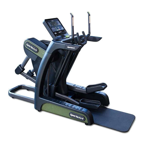
1. INTRODUCTION Congratulations on your purchase of one of the finest exercise products on the market today, the SportsArt VERSO ECO-POWR™ G886 3-in-1 Cross Trainer. Constructed of high quality materials and designed for years of reliable usage, this product was made to become an integral part of your commercial fitness venue. -
Page 4: Safety Precautions
2. SAfETy PRECAUTIONS Your SportsArt 3-in-1 Cross Trainer was designed and built for optimum safety. However certain precautions apply whenever you use your 3-in-1 Cross Trainer. Please read the entire manual before assembly and operation. Also, please note the following safety precautions: ●... - Page 5 2. SAfETy PRECAUTIONS (CONTINUED) ● Children 12 or younger should be supervised to ensure that they do not play on or near the product.. ● Maintenance and repair must be performed by trained service personnel only. Improper maintenance would not only damage the machine, but also may present a danger to the exerciser.
- Page 6 2. SAfETy PRECAUTIONS (CONTINUED) If you are a French speaking person in North America, please place the following label contained in the owner’s manual on the console as shown. Customers outside of North America will not receive this French warning label.
- Page 7 2. CONSIGNES DE SéCURITé • Votre cross trainer SportsArt a été conçu et fabriqué afin d’assurer une sécurité optimale. Cependant certaines précautions s’appliquent chaque fois que vous utilisez votre tapis de course. • Lisez entièrement le manuel avant l’assemblage et l’utilisation. Veuillez aussi noter les consignes de sécurité...
- Page 8 2. CONSIGNES DE SéCURITé (SUITE) ATTENTION Si vous ressentez une douleur ou si vous avez une sensation anormale, ARRÊTEZ VOTRE ENTRAÎNEMENT et consultez immédiatement votre médecin. Entraînez-vous à votre niveau d’exercice recommandé. NE PAS s’entraîner jusqu’à l’épuisement. Avant de commencer un programme d’exercice, vous devriez consulter votre médecin.
-
Page 9: List Of Parts
3. LIST Of PARTS Assembly Parts Name Qty. No. Name Qty. A1 Main frame Hardware kit A2 Front support assembly A10 Mat Right pedestal side Left support tube end cover Right support tube end A4 Owner’s manual A5 Pivot cover A13 Left PU handle Right footplate A14 Right PU handle... - Page 10 3. LIST Of PARTS (CONTINUED) Components in the Hardware Kit Name Qty. Specification Notes Mushroom head Phillips self M4*L12 tapping screw Round head Phillips screw M5*P0.8*L10 Soft cap Screwdriver bit Flat and Phillips L-shaped Allen wrench T-shaped Allen wrench Double open-end wrench 8*17mm Yellow/Green Ground wire...
-
Page 11: Assemble The Product
4. ASSEMBLE THE PRODUCT Follow instructions below to assemble this product. Note that in this manual the words “left” and “right” are used to refer to the product and its parts. As such, these designations correspond to the “left” and “right” sides of a person in position to exercise on this product. - Page 12 STEP 1 Prepare for Assembly (Continued) (d) Remove screws from the main frame (A1) attached to the pallet. (e) Grasp the pallet and then have two people to grasp the front support assembly (A2) with both hands and rotate the main frame counterclockwise to move it out of the pallet as shown.
-
Page 13: Step 2 Install The Main Frame
STEP 2 Install the Main frame Please follow instructions (a) through (d) to install the main frame. (a) Handle installation: Remove screws (35) from the main frame as shown. Insert the left PU handle (A13) and press the left PU handle (A13) forward slightly when securing screws (35). - Page 14 STEP 2 Install the Main frame (Continued) (c) Press the left/right pedestal side cover (A8) (A3) into place as shown. (d) Remove the last anti-slip insert (36) from the main frame and then remove screws (37). Set the left support tube end cap (A11) into place and then press it forward slightly when securing with screws (37).
-
Page 15: Step 3 Move The Product Into Place
STEP 3 Move the Product into Place (Note: For safety, two people are required for this procedure.) Stand on the left and right sides. Grip the handle in area A with one hand, another hand on the left/right support tube as shown). Simultaneously lift the unit and roll it into place for use. -
Page 16: Step 4 Level The Product
STEP 4 Level the Product For the user’s safety and the proper functioning of the product, this 3-in-1 cross trainer must sit level on a flat floor. If necessary, adjust the levelers by following instructions (a) through (c) below. (a) Loosen the leveler nut. (b) Rotate the leveler foot downward so it firmly touches the floor. -
Page 17: Step 5 Install The Front Support Assembly
STEP 5 Install the front Support Assembly Remove the set pins (33) attached to the main frame and then secure the front support assembly (A2) to the main frame with the set pins (33) as shown. (Note: Make sure to remove the front support assembly that is for the safety before moving the product.) -
Page 18: Step 6 Place The Mat
STEP 6 Place the Mat Place the mat (A10) as shown below. -
Page 19: Step 7 Install The Power Cord
STEP 7 Install the Power Cord (a) Insert the power cord plug into the connector on the product. (b) Secure power cord connector screws (124) and then insert the other end of the power cord into the appropriate power supply socket in the wall. -
Page 20: Step 8 Unit Inspection
STEP 8 Unit Inspection After completing the assembly, please follow instructions (a) through (b) below to inspect the unit. (a) Before plugging the power cord, make sure the unit is steady and on a level surface. If the unit is not steady, make adjustments according to the instructions “Level the product”... -
Page 21: Step 9 Beware Of Moving Parts
STEP 9 Beware of Moving Parts This product has moving parts that could be a danger to people and animals. During use, do not insert hands or other objects into the left/right footplate assembly, the opening in the pivot cover, or other areas in which such action might present a hazard. -
Page 22: Understand The G886 Display
5. UNDERSTAND THE G886 DISPLAy DISPLAy Overview The VERSO ECO-POWR™ G886 3-in-1 Cross Trainer is designed for user convenience. With better feedback about your workout, you get better results. The following explains the display key and window functions. Please read this manual, understand the display functions, and thereby get optimum enjoyment and benefit from this product. - Page 23 DISPLAy Keys (Continued) Name function Press a workout program key (MANUAL, INTERVAL, PLATEAU, RANDOM, TRACK, FIT PROGRAM TEST , CUSTOM HR, WT LOSS CARDIO) to select your preferred workout. ▲ ▼ LENGTH Press the key to adjust the length settings. After making a selection, press this key to confirm ENTER your choice.
-
Page 24: Display Exercise Feedback Window
DISPLAy Exercise feedback Window Description Actual heart rate (By holding the sensors with two hands.) YOUR GRID Wh: Total accumulative GRID Wh. WEIGHT LOSS ZONE: WT LOSS 65% heart rate values. Displays reminding message or workout program illustrations. TIME: Total accumulative time or remaining time of workout goal time. -
Page 25: Display Specifications
DISPLAy Specifications Information Specifications RESISTANCE 1 ~ 40 STEPPER → LENGTH: 1/ HEIHGT: 1 ~ 3 STRIDE LENGTH BIKE → LENGTH: 1 ~ 3/ HEIHGT: 1 ~ 3 STRIDE HEIHGT ELLIPTICAL → LENGTH: 1 ~ 9/ HEIHGT: 1 ~ 3 CAL/HR 0 ~ 9999 K-CAL TIME... -
Page 26: Operate The Product
6. OPERATE THE PRODUCT OPERATION Safety Operating Area (a) Safety clearance required as shown below. Do not allow people to be near this area when operating. (b) Noise emission under load is higher than without load. -
Page 27: Operation Safety Get On/Off
OPERATION Safety Get On/Off (a) Place your feet on floor and then hold the handles to steady self while stepping one foot onto the lowest pedal as shown below. (b) Wait until pedals come to a complete stop and then hold onto handles for stability while carefully stepping off the product. -
Page 28: Operation Proper Workout Position
OPERATION Proper Workout Position (a) User proper workout position as shown below. (b) Over exercise or improper workout position may result in serious injury. (c) User can hold onto handles for stability when getting on or getting off from the right/left side of the product. (d) This product is intended for exercise arms and legs. -
Page 29: Operation Assistive Handle Switch
OPERATION Assistive Handle Switch LENGTH function allow user to change the stride length of the device according to their actual stride. HEIGHT function allow user to change the stride height of the device according to their actual stride. RESISTANCE function allow user to change the resistance level of the device according to actual force that foot can exert. -
Page 30: Operation Start Screen
OPERATION Start Screen Press the wake-up key located in the bottom-right corner of the display or pedal the cross trainer, after hearing a “beep” sound, the display will show the start screen of G886 as shown below. OPERATION Quick Start In QUICK START mode, the default MODE is ELLIPTICAL and the default PROGRAM is MANUAL;... -
Page 31: Operation Start A Workout Program
OPERATION Start a Workout Program 1. Mode Settings Select STEPPER , BIKE or ELLIPTICAL mode from the mode menu on the left side of the display. Press STEPPER key , BIKE key or ELLIPTICAL key then press the ENTER key to confirm your selection. - Page 32 OPERATION Start a Workout Program (Continued) • The CALORIE setting range is from 100 to 9999 kCal, with a default value of 100 kCal. • The Watt-hour TO GRID setting range is from 5 to 100 Wh, with a default value of 20Wh.
-
Page 33: Operation Display
OPERATION Display 1. ”STEP TO START” will appear in the illustration/message window before pedaling. 2. During workout, you can switch to a different Mode or Workout Program. 3. Stride length/height cannot be adjusted if the speed is under 20SPM. The message ”NO STRIDE ADJUST UNDER 20 SPM” will appear on the illustration/message window. -
Page 34: Operation Pause
OPERATION Pause In Workout mode, press STOP/PAUSE key to pause the program. The illustration/message window will show messages “PAUSED” and “PRESS QUICK START TO RESUME”. All the workout data will stop accumulating and remain at the current values. If no operations in 20 second, enter Idle mode. -
Page 35: Operation Workout Programs
OPERATION Workout Programs Select your desired program from the mode menu in the bottom-left corner of the display. The following explains features of the workout programs. MANUAL This program allows you to manually control resistance, stride length and stride height. INTERVAL There are three interval programs: 1:1, 1:2, 2:2. - Page 36 OPERATION Workout Programs PLATEAU Resistance levels in this workout gradually increase, level off, then gradually decrease. The first and last segments of this workout each occupy 20% of the workout. The middle segment occupies 60% of the workout. Follow prompts to establish your workout goal.
- Page 37 OPERATION Workout Programs (Continued) BIKE MODE (1) The best RPM range during test is 45 to 55RPM with targeted 50RPM. If the actual RPM is below 45RPM or above 55RPM, the console will show “MAINTAIN RPM- 50” for 5 seconds. (2) Fit Test Stages Heart rate and workload during different stages Heart...
- Page 38 OPERATION Workout Programs (Continued) The difference in heart rate between the extended minute and the previous minute is subject to conditions a, b, and c to determine how the test proceeds. Additional Stages: Results are determined according to a, b and c conditions of Stage 2, 3 and 4.
- Page 39 46.8 44.6 41.8 38.5 35.3 44.2 42.4 39.9 36.7 33.6 42.5 41.0 38.1 35.2 31.8 41.0 38.9 36.7 33.8 30.2 39.5 37.4 35.1 32.3 28.7 37.1 35.4 33.0 30.2 26.5 OPERATION Workout Programs (Continued) 34.5 32.5 30.9 28.0 23.1 Percentile Values For Maximal Aerobic Power(ml.kg .min )--Women Percentile...
- Page 40 OPERATION Workout Programs (Continued) (5) Following conditions occurs will end this test program: a. STOP key is pressed. b. Program time ends. c. Actual Heart Rate is > (220-Age) x 0.8 for more than 15 seconds. d. No heart rate detected for more than 30 seconds. e.
-
Page 41: Operation Review Summary
OPERATION REVIEW SUMMARy Press STOP/PAUSE key two times to end workout and then the message “REVIEW SUMMARY” will appear, along with accumulated workout information for 15 seconds,. Press STOP/PAUSE again to return to Banner page. OPERATION User Preference & Component Version Basic settings determine units of measure and show total distance and time, along with display/drive board program version numbers. - Page 42 OPERATION User Preference & Component Version (Cont.) (4) TOTAL TIME “TIME - xxxxxx HOURS” will scroll across the illustration/message window, press the ENTER key to view total energy created. (5) TOTAL ENERGy “WATTS - xxxxxx KWH” will scroll across the illustration/message window, press the ENTER key to view product serial number.
-
Page 43: About Heart Rate Detection
7. ABOUT HEART RATE DETECTION Heart rate detection functions are selected at the time of purchase. Not every product has every type of heart rate detection. The following explains factors that influence the performance of two of the most common types of heart rate detection devices. -
Page 44: Guidelines For Exercise
8. GUIDELINES fOR EXERCISE HOW HARD SHOULD I EXERCISE? Studies show that to benefit from aerobic exercise, people need to maintain a certain heart rate during their workouts. Your heart rate training zone depends on your age and fitness level. The darkened area in the chart to the right represents the recommended heart rate training zone for people of various ages. -
Page 45: Micro Inverter
9. MICRO INVERTER MI-250 MICRO INVERTER Important Safety Instructions CAUTION These servicing instructions are for use by qualified personnel only. To reduce the risk of electric shock, do not perform any servicing other than that specified in the operating instructions unless you are qualified to do so. PRUDENCE! Ces instructions d’entretien sont uniquement destinées à... - Page 46 MICRO INVERTER Cautionary Messages (Continued) WARNING Power fed from more than one source. Each circuit must be individually disconnected before servicing. Do not remove cover until 5 minute after disconnecting all sources of supply. AVERTISSEMENT! L’alimentation provient de plus d’une śource. Chaque circuit doit étre coupé avant toute intervention de dépannage.
-
Page 47: Micro Inverter Electronic Specifications
MICRO INVERTER Electronic Specifications Input Data(3 Phase AC) 3 Phase permanent-magnet Input power source generator Maximum input voltage 140V(line-to-line voltage) Nominal operating voltage range 55-125V(line-to-line voltage) Maximum input current 7A(line current) Output Data(single phase AC) Maximum continuous output power 220W Output power factor rating >0.9 120VAC(105.6-132.0V) (for USA) -
Page 48: Micro Inverter Circuit Board & Product Settings
MICRO INVERTER Circuit Board & Product Settings frequency setting: MI-250 can detect the frequency automatically without setting. Connecting to grid power: After MI-250 is installed into Green System products, the power can be linked to grid power through product power cord, as shown in the following figure. - Page 49 MICRO INVERTER Circuit Board & Product Settings (Cont.) This optional accessory SportsArt Eco-Powr Daisy Chain unit connection cord is suitable SportsArt Eco-Powr Daisy Chain cable unit connection cable allows multiple Eco-Powr products to be powered from a single electrical socket. SportsArt Eco-Powr Products 4th...
-
Page 50: Maintenance
10. MAINTENANCE Maintenance topics are presented below in the following order: error messages, lubrication the seat carriage, maintenance schedule, task list, one-year maintenance log, and electronics block diagram. MAINTENANCE Safety Precautions ● Please follow standard safety precautions when servicing on this product. ●... -
Page 51: Maintenance Error Messages
MAINTENANCE Error Messages Error messages can appear on the cross trainer as a troubleshooting aid. Error messages appear in the following format: “ERROR _X_Y”. X represents the category of the error. Y represents the specific issue. Error code explanations are as follows: Error Error Explanation... - Page 52 OPERATION Error Messages (Cont.) Error Error Explanation Description code X code y DC BUS voltage is too high. DC BUS error Force warm up. Force jump (EngStop). Generator over current Generator voltage error Generator too hot The right stride length control motor is abnormal.
-
Page 53: Maintenance Circuit Breaker
MAINTENANCE Circuit Breaker (a) A circuit breaker is an automatically operated electrical switch designed to protect an electrical circuit from damage caused by overcurrent/ overload or short circuit. A spring located under the push button causes the button at area D to lift up and the breaker to trip as shown. (b) After the fault is repaired by qualified technicians, press the push button to reset circuit breaker to resume normal operation as shown. -
Page 54: Maintenance Disassemble The Product
MAINTENANCE Disassemble the Product Please follow instructions (a) through (e) in sequence to disassemble the product as shown below. (a) Display (b) Stride Support Assy. of Height (Note: Must be performed by trained service personnel only.) - Page 55 MAINTENANCE Disassemble the Product (Continued) (c) Resistance Key (d) Stride Support Assy. of Length (Note: Must be performed by trained service personnel only.)
- Page 56 MAINTENANCE Disassemble the Product (Continued) (e) Drive Board and Stride Motor Assy. (Note: Must be performed by trained service personnel only.)
-
Page 57: Maintenance Schedule
MAINTENANCE Schedule Area Week Month Quarter year Notes Exterior Clean Inspect and Screws secure loose parts... -
Page 58: Maintenance Task List
MAINTENANCE Task List Like cars, fitness products require maintenance. Regular maintenance extends product life, and failure to maintain products can void the manufacturer’s warranty. Copy the maintenance log sheet, and record maintenance work for each fitness product. Daily tasks 1. Use a clean, lint-free towel, dampened with a mixture of Simple Green® all-purpose cleaner and water, to thoroughly clean the product exterior. -
Page 59: Maintenance One-Year Maintenance Log
MAINTENANCE One-year Maintenance Log Facility:_______________________ Supervisor:____________________ Product model number:__________ Serial number:_________________ Start date: ____________________ End date:_____________________ Daily Tasks Weeks 1-7 Weeks 8-14 Weeks 15-21 Week 22-28 Completed Daily Tasks Week 29-35 Week 36-42 Week 43-49 Week 50-52 Completed Weekly Tasks Weeks 1-7 Weeks 8-14 Weeks 15-21 Weeks 22-28... -
Page 60: Accessories
11. ACCESSORIES These accessories are related to the functions of this machine. Some are standard and others are optional. The details of each accessory and its function are explained. USB CHARGER (Standard) The USB charger will provide 5V and 1A voltage for charging of smart phone or other devices. -
Page 61: Accessories Entertainment Cap
ACCESSORIES Entertainment Cap Item Name function USB port This port is used for data transferring. When a smart phone is connected with equipment, Bluetooth/ press this button to disconnect. Scan the QR code WIFI button or touch the NFC tag on the console to connect to the equipment again if necessary. -
Page 62: Accessories Mye Wireless Tv Audio_Channel Receivers
ACCESSORIES MyE Wireless TV Audio_Channel Receivers [To purchase, please contact MYE Inc. http://www.myeclubtv.com/] Multiple TV and audio channels receiving and volume adjustment enabled. ● The following two modules are available for this receiver (to be purchased by client) 1. MC3R-9(900MHZ), which has to be used with a MYE Wireless TV Digital Audio Channel Transmitter MWTD-S9. -
Page 63: Accessories Options
ACCESSORIES Options 1. External Mount TV Bracket... -
Page 64: Appendixes
12. APPENDIXES APPENDIXES Specifications Model G886 L : 2615 mm (103”) Dimensions W : 940 mm (37”) H : 1780 mm (70.1”) Overall Weight 272 kg (599 lbs) Maximum User Weight 150 kg (330 lbs) 100 – 120 V / 60 Hz (USA) Power Requirement 220 –... -
Page 65: Appendixes Electronics Block Diagram
APPENDIXES Electronics Block Diagram LCD Display Board SA WELL+ SA WELL Option Connection key Numeric Key Key Board Board HTR Board SA WELL Board USB Board Control Board RFID Board T_USB Board EUP Board Headphone Board LENGTH HEIGHT CRANK Rocker Board Board Stepper Motor... - Page 66 your Authorized Distributor...
Need help?
Do you have a question about the VERSO ECO-POWR G886 and is the answer not in the manual?
Questions and answers