Table of Contents
Advertisement
Quick Links
Download this manual
See also:
Repair Manual
-
SAFETY PRECAUTIONS....................................................................
1.1 SAFETY PRECAUTIONS....................................................................................
1.2 ABOUT THIS MANUAL........................................................................................
-
UNPACKING THE S770 PINNACLE TRAINER...................................
2.1 INTRODUCTION.................................................................................................
2.2 SPECIFICATIONS...............................................................................................
2.3 COMPONENTS IN THE CARTON......................................................................
2.4 COMPONENTS IN THE HARDWARE KIT..........................................................
2.5 COMPONENTS ON THE PRODUCT..................................................................
-
PRODUCT ASSEMBLY........................................................................
3.1 INSTALLATION REQUIREMENTS.....................................................................
3.2 ASSEMBLY INSTRUCTIONS.............................................................................
-
OPERATING INSTRUCTIONS...........................................................
4.1 EXPLANATION OF FUNCTIONS.......................................................................
4.2 OPERATING ILLUSTRATIONS..........................................................................
4.3 UNIT MAINTENANCE........................................................................................
-
UNDERSTANDING THE S770 DISPLAY CONSOLE........................
5.1 DISPLAY FEATURES.........................................................................................
5.2 DISPLAY FUNCTIONS.......................................................................................
5.3 DISPLAY INFORMATION...................................................................................
5.4 BUTTON FUNCTIONS.......................................................................................
-
HOW TO OPERATE YOUR S770 PINNACLE TRAINER........................
6.1 QUICK START.....................................................................................................
6.2 WORKOUT SETUP.............................................................................................
6.3 OPERATING PROCEDURE DURING EXERCISE.............................................
6.4 COOL DOWN......................................................................................................
6.5 POWER SAVING MODE.....................................................................................
-
7.1 ABOUT TELEMETRY HEART RATE...................................................................
7.2 ABOUT CONTACT HEART RATE.......................................................................
TABLE OF CONTENTS
1
1
2
3
3
4
4
5
6
8
8
8
38
38
39
41
43
43
44
45
45
46
46
46
47
47
47
48
48
48
Advertisement
Table of Contents

Subscribe to Our Youtube Channel
Related Manuals for SportsArt Fitness S770


Summary of Contents for SportsArt Fitness S770
-
Page 1: Table Of Contents
5.1 DISPLAY FEATURES..................5.2 DISPLAY FUNCTIONS..................5.3 DISPLAY INFORMATION................... 5.4 BUTTON FUNCTIONS..................- CHAPTER 6 HOW TO OPERATE YOUR S770 PINNACLE TRAINER......6.1 QUICK START..................... 6.2 WORKOUT SETUP..................... 6.3 OPERATING PROCEDURE DURING EXERCISE..........6.4 COOL DOWN...................... 6.5 POWER SAVING MODE.................. - Page 2 - CHAPTER 8 OVERVIEW OF PROGRAMS..............8.1 MANUAL......................8.2 MOUNTAIN MODE..................... 8.3 PLATEAU......................8.4 INTERVAL(1:1, 1:2, 2:2)..................8.5 FAT TEST......................8.6 FIT TEST......................8.7 WT LOSS & CARDIO & CUSTOM HR............... CHAPTER 9 USER PARAMETER SETTING............9.1 USB PORT......................9.2 Cardio Theater....................9.3 RJ45 SOCKET FOR CSAFE................
-
Page 3: Chapter 1 Safety Precautions
SportsArt Service Department or your authorized service dealer for repairs. ˙ Use SportsArt factory parts when replacing parts. Do not use parts or accessories that are not recommended by the manufacturer. ˙ Do not modify the unit in any way unless required to do so by SportsArt Fitness. -
Page 4: About This Manual
1.2 ABOUT THIS MANUAL This manual provides instructions for the assembly, installation, and operation of the SportsArt S770 Pinnacle Trainer. Please study this manual thoroughly to prevent injury to people and damage to the product. Please save these instructions for future reference. -
Page 5: Chapter 2 Unpacking The S770 Pinnacle Trainer
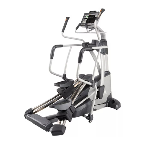
2.1 INTRODUCTION Thank you for purchasing a high quality product from SportsArt Fitness. Constructed of robust materials and built for years of trouble-free usage, the SportsArt S770 Pinnacle Trainer was designed and manufactured to become an integral part of your fitness regimen. -
Page 6: Specifications
Dimensions: 71" 43" 74 1/2" Weight: 168 KG; 370 LB 2.3 COMPONENTS IN THE CARTON The following diagram shows large parts used in the assembly of the SportsArt S770 Pinnacle Trainer. All of these parts are packed inside the shipping carton. -
Page 7: Components In The Hardware Kit
Components in the Carton Number Name Number Name Pedestal assembly Main frame body Rear base eck cover A10a Right shoulder cover Left rear cover A10b Left shoulder cover Right rear cover A10c Pedestal cover Pulley bracket A10d Cable (standard) Rocker cover A A10e Cable (short stride) Rocker cover B... -
Page 8: Components On The Product
2.5 COMPONENTS ON THE PRODUCT Some components are installed on the product. These items will be needed for product assembly. Numbers listed are used on drawings that follow. Number Name Specification Mushroom top Phillips-head screw M4*L16 M8*L25 Inner hex screw ψ... - Page 9 Note 1: At times, the word "screws" is used for conciseness in some cases where screws, washers, and other hardware are involved. Note 2. First, remove all parts and the hardware kit. Then remove the product from the box. Note 3. Adjust the leveler in area A downward until it presses the floor. Then begin product assembly.
-
Page 10: Chapter 3 Product Assembly
- CHAPTER 3 PRODUCT ASSEMBLY 3.1 INSTALLATION REQUIREMENTS The challenge of product installation depends highly on the area in which the product will be used. Stairs, doorways, and other obstacles must be considered in planning for product installation. Please ensure the safety of people and property in planning the installation of any product. - Page 11 Rear Base Installation STEP 1 1-1. First remove screws (41) and covers (A2a,A2b) from the rear base (A2) left and right sides. 1-2. Remove screws (42,43) from the bottom of the main frame (A1). 1-3. Insert the rear base (A2) into its mount on the main frame (A1). Then loosely secure screws (42,43), first in area A, then in area B.
- Page 12 Pulley Bracket Installation STEP 2 2-1. First, remove screws (42,45,46) from the pulley bracket (A3). 2-2. Cut the zip tie away from the cable (50) on the pulley bracket (A3). 2-3. Tighten screws (42,45,46) to secure the pulley bracket (A3) to its mount on the main frame (A1).
- Page 13 Left/Right Glide Track Installation STEP 3 -11-...
- Page 14 3-1. First, remove the following hardware: (45,47) from the pulley bracket (A3); (45,47) from the rear base (A2); and (41) from covers (A5a) of the left/right glide track (A5,A6). -12-...
- Page 15 3-2. Tighten screws (45,47) to secure left/right glide tracks (A5,A6) onto the pulley bracket (A3) and the rear base (A2). Note: If screws (45,47) do not thread easily, move the rear base (A2) forward and backward until screws/holes align properly. -13-...
- Page 16 3-3. Remove screws (34) from the hardware kit. Then secure screws (34) from the bottom upward, in area A and B of the left/right glide tracks (A5,A6). -14-...
- Page 17 3-4. First, secure screws (42) into area C of the rear base (A2). Then secure screws (47) into area D of the left/right glide tracks (A5,A6). -15-...
- Page 18 Cable Installation STEP 4 Note: Install the "short stride" cable A3b if you wish to restrict vertical motion. Motion will be reduced by about 4 inches. 4-1. First, remove screws (48,54) and the pin (49) from the cable mount (52) on the left/right footplates (53).
- Page 19 Pedestal Installation STEP 5 5-1. First, remove screws (47,51) from the main frame (A1) pedestal mount. 5-2. Use these screws (47,51) to secure the pedestal assembly (A10) to the main frame (A1) mount. Note: In securing the pedestal assembly (A10), keep the pedestal cover (A10d) up. 5-3.
- Page 20 Main Unit Belt Installation STEP 6 6-1. First, remove screws (41) and covers (A10e,A10f) from left/right rockers on the pedestal (A10). Then cut the zip tie off the front of the belt. Note: Do not cut the zip tie off the rear of the belt (area B). Finally, use tools to remove hardware (56,57,58,59) from the belt (55).
- Page 21 Motion Rod Installation STEP 7 7-1. Please follow steps (a,b,c,d) in order to install one motion rod (A4). (a) First, use tools to remove hardware (46,60,57,62) from the motion rod (A4). (b) Use this hardware (46,60,57,62) to secure one end of the motion rod (A4) to the mount on one rocker arm (A10).
- Page 22 Display Neck Assembly Installation STEP 8 -20-...
- Page 23 8-1. Please install parts in order (a~d). (a) First, remove the neck cover (A10a), soft cap (65), and screws (66) from the pedestal (A10). (b) Then remove screws (61,64) from the display neck assembly (A11). (c) Cut the zip tie off the data cable in area E. Note: Do not cut off the zip tie in area F.
- Page 24 8-2. First, gently pull the 4 data cables downward and backward. Then insert them into the pedestal mount. Note: act carefully to avoid damaging the cables. Secure screws (61) in area <A>. Then secure screws (64) in area <B>. Finally, insert the soft cap (65) into place. -22-...
- Page 25 8-3. To install the display neck assembly (A11) data cables, separate the cables into groups. Make the two short data cables one group. Make the two long data cables another group. First install the long data cables; then install the short data cables.
- Page 26 8-3-2. Follow steps (g~l) in order to install the short data cables. (g) Thread the two short data cables under the mount piece as shown. (h) Separate the cables by left and right side markings. (i) Connect cables according to side: left to left, right to right. (j) After connecting cables, tuck them into the mount area to avoid being pinched by the neck cover.
- Page 27 Left/Right Handle Installation STEP 9 -25-...
- Page 28 9-1. Follow steps (a~f) in order to secure left and right handles (A14,A15). (Note: Left and right handles are installed in the same way.) (a) Please remove screws (67,68) from the rocker arm axle. (b) Remove screws (41) and right and left shoulder covers (A10b,A10c). (c) Remove screws (51,69) from the handle mounts.
- Page 29 Right/Left Support Installation STEP 10 -27-...
- Page 30 10-1. First, remove screws (68,70) from support mounts and screws (71) from left/right support (A12,A13) lower covers (A12a,A12b). -28-...
- Page 31 10-2. Please follow steps (a,b,c) in order to install left/right supports (A12,A13) and support lower covers (A12a,A12b). (a) First, insert left/right supports (A12,A13) onto the rocker axle. Then secure screws (67,68) from the bottom, upward. (b) Secure cover screws (68,70) in the lower part of the left/right supports (A12, A13).
- Page 32 Left/Right Rocker Cover Installation STEP 11 11-1. Put left/right rocker covers (A10e,A10f) back in place and secure them with screws (41). -30-...
- Page 33 Pulley Cover Installation STEP 12 12-1. First, remove pulley covers (A9,A9a). Then remove screws (41,72) from the pulley mount. 12-2. Insert the pulley lower cover (A9a) onto the cable bracket (A3). Then insert screw sockets (33) from the hardware kit onto the cable mount. 12-3.
- Page 34 Footplate and Footplate Cover Installation STEP 13 13-1. Follow steps (a~e) in order to install the footplate and footplate cover. Note: Left and right sides are installed in the same fashion. (a) Remove screws (73) from the footplate mount. (b) Note that footplates are side-specific. There is a left (A8L) and a right (A8R) footplate.
- Page 35 Rear Base Cover and Left/Right Rear Covers STEP 14 14-1. First, remove screw sockets (33) from the hardware kit. Insert them into holes in the rear base as shown. 14-2. Set the rear base cover (A7) and left/right rear covers (A2a,A2b) in place. Secure them with screws (41) as shown.
- Page 36 Leveling the Unit STEP 15 15-1. Rotate leveler feet in position (A) downward as shown in diagram (a) until the rubber touches the floor. Make sure the product is level in this position. Then rotate leveler feet in position (B) and (C) so the rubber touches the floor. After making sure the product is level in all directions, rotate leveler nuts (b) upward until they press against the frame of the product.
- Page 37 Moving the Unit STEP 16 Note: When lifting or moving any heavy object, maintain proper posture to avoid injury. 16-1. Instructions for one person: Stand in the center behind the rear base. Grip the rear base in area A with both hands. Lift the rear base and roll the unit into position.
- Page 38 Replacing the Cable STEP 17 Note: There are two types of cables. Cable (A3a) is standard. Cable (A3b) is the short stride cable. -36-...
- Page 39 17-1. To replace cables, follow steps (a~e) in order. The procedure is the same for both (A3a or A3b) cables. (a) Remove screws (41,72) and the pulley cover (A9). (b) Remove pulley cover (A9a). (c) Remove the pulley screws (48,54), axle (49), cable (A3aorA3b), and cable washer (35) from one side.
-
Page 40: Chapter 4 Operating Instructions
- CHAPTER 4 OPERATING INSTRUCTIONS 4.1 EXPLANATION OF FUNCTIONS Left/right handles have toggle switches in position A. Press the "+" toggle to increase resistance: LEVEL1~LEVEL20. Press the "-" toggle to decrease resistance: LEVEL20 ~LEVEL1. Area B is the contact heart rate plate. To operate contact heart rate, place area C of your hand on the contact heart rate plate. -
Page 41: Operating Illustrations
4.2 Operating Illustrations Illustration 1 Illustration 2 -39-... - Page 42 Illustration 3 Illustration 4 -40-...
-
Page 43: Unit Maintenance
4.3 Unit Maintenance In area A, put silicone lubricant on left/right glide track rails (A5,A6). Method: (a) Use a clean, lint-free cloth to wipe dust and dirt off left/right glide track rails (A5,A6) daily. (b) Move footplates to inspect left/right glide rail (A5,A6) operation smoothness. (c) Repeat steps (a) and (b) 2~3 times, this time applying silicone lubricant on the cloth. - Page 44 Cautionary notes regard the following: (a) elastic cord, (b) belt, (c) cable. 1. The elastic cord, belt, and cable are wear items. Replace them as necessary on a regular schedule. 2. The elastic cord, belt, and cable must be inspected after the first year. Thereafter, inspect these parts once a month.
-
Page 45: Chapter 5 Understanding The S770 Display Console
- CHAPTER 5 UNDERSTANDING THE S770 DISPLAY CONSOLE 5.1 Display Features Workout Goal 65% HR Real 80% HR Heart Rate Information Setting Panel Target Heart Rate Target Window Programs UP/DN & Setting Resistance Workout Goal Dot Matrix numeric keypad Window... -
Page 46: Display Functions
5.2 Display Functions 1. WORKOUT LEVEL (level of resistance): 1 to 20 2. TIME (total time accumulated): 0:00 to 99:59 3. DISTANCE (total distance accumulated): 0.0 to 9999 Km or Miles 4. CALORIES (total calories burned): 0.0 to 9999 K-CAL 5. - Page 47 6. NUMERIC KEYPAD (0 to 9) ▲ ▼ The numeric keypad can replace the function of < / > buttons. Simply enter ▲ ▼ numbers (0 to 9) on the numeric keypad rather than pressing < / > buttons. 7. DECIMAL POINT KEYPAD ( . ) Use this key to enter the decimal point of a setup value.
-
Page 48: Chapter 6 - How To Operate Your S770 Pinnacle Trainer
- CHAPTER 6 HOW TO OPERATE THE S770 PINNACLE TRAINER 6.1 QUICK START If you begin a workout via QUICK START, resistance begins at level one. You can modify the resistance level at any time during the workout. The system default values are Weight 165 lbs (75 kgs) and Age 35. -
Page 49: Operating Procedure During Exercise
6.3 OPERATING PROCEDURE DURING EXERCISE A. Information will appear in each window as follows: 1. Information window: Workout information is shown every 6 seconds. DISPLAY LOCK/UNLOCK can be activated. 2. WORKOUT GOAT Percentage Complete: This window shows the percentage of the workout completed. -
Page 50: Chapter 7 - About The Heart Rate Detection And Presentation
- CHAPTER 7 ABOUT THE HEART RATE DETECTION AND PRESENTATION 7.1 ABOUT TELEMETRY HEART RATE The word "telemetry heart rate" refers to the detection of the heart rate, usually via a strap worn on the exerciser's chest, and transmitted over the air for reception by a receiver built into the product. - Page 51 4.The vibration of treadmills at speeds over 4mph/6.4kph makes heart rate detection difficult. Also, if your hands move, heart rate detection becomes difficult. Suggestions: For better heart rate detection, keep hands in one place on the contact plates. Or wear a telemetry heart rate strap on your chest. Note: Avoid Static Electricity In cold, dry areas, static electricity can interfere with unit operation.
-
Page 52: Overview Of Programs
- CHAPTER 8 OVERVIEW OF PROGRAMS 8.1 MANUAL This program allows you to adjust the level of resistance manually by pressing ▲ ▼ WORKOUT LEVEL keys. 8.2 MOUNTAIN MODE Mountain program has an infinite number of programs. Continue to press this button until you find your desired course. -
Page 53: Fit Test
8.6 FIT TEST This program tests the user's cardiovascular fitness. Once the test is completed, a message appears on the screen: "END OF FIT TEST" "YOUR SCORE IS ???". ( ??? is a place holder for the number shown. ) The score can range from 0 to 100, with 100 being optimum. -
Page 54: User Parameter Setting
- CHAPTER 9 USER PARAMETER SETTING To check the system default setting, at the start up screen (select PROGRAM or QUICK START). Hold the ENTER key for 3 seconds: ▲ ▼ 1. Unit of Speed (MPH or KPH): Press keys to change the speed unit setting. Press ENTER to confirm your choice and to see the next setting. -
Page 55: Cardio Theater
9.2 Cardio Theater This port provides 5 VDC power supply for Cardio Theater devices which allow reception of various channel audio signals. 9.3 RJ45 SOCKET FOR CSAFE This RJ45 connector is for CSAFE signal transmission associated with the FitLinxx company. 9.4 DC 33V/2A This connector is designed for recharging the product's internal battery. -
Page 56: Chapter 10 About Standard And Short Stride Cables
CHAPTER 10 - NOTE ON STANDARD AND SHORT STRIDE CABLES The following chart lists differences between short stride cable and standard cables: Item Standard cable Short stride cable*** Provided in box B in the main Installed on product Installation carton Provides maximum travel Provides about 4 inches less Usage... -
Page 57: Wiring Schematic
WIRING SCHEMATIC Your Authorized SPORTS ART Distributor -55-...
Need help?
Do you have a question about the S770 and is the answer not in the manual?
Questions and answers