Advertisement
Quick Links
Advertisement

Related Manuals for SportsArt Fitness G572R


Summary of Contents for SportsArt Fitness G572R
- Page 1 G572R Repair Manual...
- Page 2 1-2-1. Display -G572R 1-3-1. Component Placement-G572R Display 1-3-2. Component Placement-G572R Lower Compartment 1-4-1. Display Block Diagram-G572R 1-5-1. Cable Connections -G572R Display Board 1-5-2. Cable Connections -G572R Drive Board 1-6-1. Indicator LEDs-G572R Display Board 1-6-2. Indicator LEDs-G572R Drive Board 1-7-1. Electronic Specifications-G572R 2-1-1.
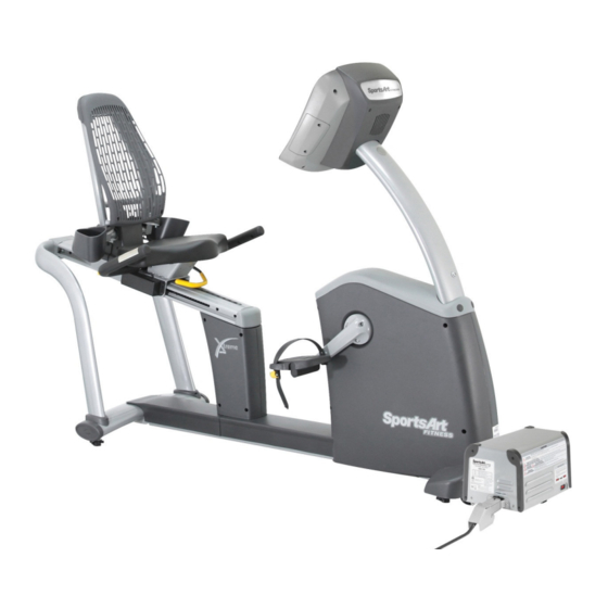
- Page 3 1-1. Product Illustration - G572R Inverter Body Inverter bypass Boost converter 1-1-1...
- Page 4 1-2. Display - G572R 1-2-1...
- Page 5 1-3. Component Placement - G572R Display 1-3-1...
- Page 6 1-3. Component Placement - G572R Display Lower Cover CASFE/USB board Fan motor 1-3-2 1-3-2...
- Page 7 1-3. Component Placement - G572R Lower Cable Connector Drive Board Cable Connector Lower Front Alternator Power Cord Connector Date Cable Connector On / Off Switch...
- Page 8 1-3. Component Placement - G572R Boost Converter DSP board 1-3-4...
- Page 9 1-3. Component Placement – Heart Rate Components in Rear Heart touch rate (HTR) HTR coiled cable sensors Connects HTR board to HTR bridge board HTR board HTR bridge board 1-3-5...
- Page 10 1-4. G572R Display Block Diagram Soft keys HR receiver CSAFEboard Display iPod board Fan motor board Sensor – L Sensor – R Drive bridge board Alternator Speed sensor Alternator Communication 24 V voltage signal Connects to other Boost converter Inverter...
- Page 11 1-4-1 1-5. Wire Connections - G572R Display To fan motor To drive board iPod earphone jack To USB/CSAFE board iPod volume and iPod decoder board power To telemetry heart rate 1-5-1...
- Page 12 1-5. Wire Connections - G572R Display (iPod iPod decoder board iPod decoder board...
- Page 13 1-5-2 1-5. Wire Connections - G572R Display (Lower Cover)
- Page 14 1-5-3 1-5. Wire Connections - G572R Drive Board Wire Connections CN4 connects to boost converter CN2 connects to display signal cable CN6 connects to boost converter (alternator) cable CN7 connects to boost converter 12V output power supply CN9 connects CN5 connects to HTR board...
- Page 15 1-5-4 1-5.Wire Connections - Boost Converter To boost converter resistor thermal switch To alternator To resistor fan To drive board 24V/12V Alternator fuse 6.3A To resistor mode switch To inverterpower cord DSP board Cable - drive board to boost converter...
- Page 16 1-5-5 1-6.G572R Display Indicator LEDs LED POWER Lit indicates there is power supply LED COMM Flashing indicates normal communication...
- Page 17 1-6-1 1-6-1. G572R/U Drive Board Indicator LEDs LED5 12V power supply Alternator fuse 6.3A...
- Page 18 1-6-2 1-6-1. C572R/U Booster Converter Indicator LEDs Alternator fuse 6.3A...
- Page 19 1-6-2 1-7. G572R Display Specification Table Specification name Details Notes Power source Grid power 220V, with inverter and boost converter Alternator AC alternator Resistance control Alternator resistance control circuit Maximum power creation 250-100 HW Speed sensor Infrared sensor Resistance range...
- Page 20 2-1.G572R/U Electronic Component Troubleshooting Malfunction Failure symptoms Points to inspect and test Components to Notes replace Cannot turn on When the display is not lit, I 1. Inspect all cable connections. 1. Drive board fuse or exercise on the product, but the 2.
- Page 21 3. Inspect whether the RPM value appears when you exercise. If not, inspect the sensor LED. Heavy I press the resistance keys on the 1. Inspect cable connections. 1.Drive board resistance display, but resistance strength is 2. Replace the drive board. The issue is always the same.
- Page 22 2-1-1 2-1.G572R/U Electronic Component Troubleshooting Contact heart Contact heart rate malfunction 1. Inspect the HTR cable connection to the 1.HTR board rate bridge board. malfunction 2. Inspect the HTR signal indicator LED. 3. Replace the HTR board. Keys don’t operate, or they 1.
- Page 23 Troubleshooting Model: G572R Display Malfunction: Unit will not start (alternator startup). Failure symptom: Exercise on the unit. The display does not light. Pedestal cable Possible cause: 1. Cables are disconnected. 2. The drive board fuse has broken. Troubleshooting: 1. Inspect all cable connections. Is the data cable connected? LED2 POWER indicator 2.
- Page 24 Input 24VDC power Boost converter 24V output to fitness Power switch (24V) Alternator 6.3A fuse Inverter310VDC output to boost converter...
- Page 25 6.3A fuse...
- Page 26 5V power...
- Page 27 Troubleshooting Model: G572R Malfunction: No RPM value appears. Failure symptom: Exercise. No RPM value appears. Possible cause: 1.Sensor signal malfunction 2. Display and boost converter signal malfunction Troubleshooting: 1. Restart the unit as a test. 2. Inspect the distance between the sensor and reflective sticker:3-8mm.
- Page 28 Troubleshooting Model: G572R Alternator cable Malfunction: No resistance connector Failure symptom: Exercise. There is no resistance. Possible causes: 1.There is no RPM signal. 2. Optic sensor malfunction 3. Boost convertor or drive board malfunction Troubleshooting: 1.Start unit again as a test.
- Page 29 Troubleshooting Model: G572R Display Malfunction: The fan does not operate. Failure symptom: Press the fan key. The fan does not operate. Possible causes: 1. Pedal rotation is below 50RPM. 2. Fan motor is malfunctioning. Troubleshooting: 1.RPM must exceed 50RPM to activate the fan.
- Page 30 Troubleshooting Model: G572R/U Display Malfunction: No telemetry heart rate reading appears. Failure symptom: No telemetry heart rate reading appears. Possible causes: 1.Battery voltage on the telemetry strap is too low. 2. Telemetry receiver malfunction 3. Environmental interference, for instance, from lights, speakers Troubleshooting: 1.
- Page 31 Troubleshooting Model: G872 Soft keys Malfunction: Key malfunction – soft keys Failure symptom: Press display keys. There is no reaction. Possible causes: 1. Soft key malfunction Troubleshooting: 1. Replace soft keys Display board Soft key 3-8-1...
- Page 32 Troubleshooting Model: G872 Key switch Malfunction: Key malfunction - display Failure symptom: Nothing happens when you press the key. Or the key operates continuously. Keys:<STOP> , LEVEL <▲> , LEVEL <▼> Possible cause: 1. Display key malfunction 2. Key switch cushion is not in place. Troubleshooting: 1.
- Page 33 Troubleshooting Model: G572R HTR board indicator LEDs Malfunction:Contact HTR heart rate malfunction Name Explanation LED1 POLAR heart rate Flashing indicates incoming POLAR Failure symptom: Hold HTR contacts. Heart rate value is indicator signal not accurate. LED2 HTR signal Lit indicates contact with HTRE sensors Possible causes: 1.HTR wire malfunction...
- Page 34 Other Topics Model: G572R Item: KPH/MPH setting, total distance, total time, total electric production, display program version, drive board program version Procedure: 1.At startup screen, press and hold the <ENTER> key for three seconds. A. Unit setting The display shows “UNIT - MPH”(imperial)or ”UNIT - KPH” (metric) units Press <▲/▼>...
- Page 35 Other Topics Model: G572R Item: Amount of units in a pod (establishes maximum power productionperfitness product) Operation: 1. Explanation A.From one to twenty Green System fitness products can be in one pod. (A pod is one inverter and the fitness products in its group.) B.
- Page 36 Other Topics Model: G572R Item: Error messages 1. A flashing line “---“ on the display indicates that the unit has entered the power saving mode. 2. When the display shows “NOT GRID”, the fitness products are in resistor mode. The alternator output is limited to 100W.
- Page 37 Other Topics Model: G572R Item: Power production display Procedure: 1. The GREEN ENERGY-OUTPUT RATIOwindow shows output in percent. 2. Simultaneously press <▲>+<▼>keys to see output wattage in the setting window. Then simultaneously press <▲>+<▼>keys to shut off the output wattage display.
- Page 38 Other Topics – Drive Board Cable Connections CN2 TO CTL To booster converter CN5 HTR CN6 Power_out CN8 DC_IN CN3 SPEED Connector Name From Explanation TO CTL Drive board Display board Display to drive board signal communication SPEED Speed sensor Drive board Sent to drive board for calculations Signal cable...
- Page 39 Inspect and Measure Part: Speed sensor Item: Infrared optic sensor Procedure: 1.Inspect the optic sensor cable connection. 2. Make sure the distance between the optic sensor head and the reflective sticker is 4-8mm. 3. Exercise at one rotation per minute. Inspect that RPM=60. At one rotation per minute, the RPM value on the display should equal 60.
- Page 40 Inspect and Measure Part: Drive board Item: Power measurement Procedure: 1.Set the voltmeter to the 30VDC or higher setting. Turn on power. 2. Place probes separately on connector wires, one on the black wire, one on the white wire. Test input at 24V. 3.
- Page 41 Inspect and Measure Part: Alternator Item: Alternator inspection Procedure: 1.Set the voltmeter to the VAC setting. Pedal the bike. Place probes on drive board CON9 wires as follows to see AC voltage values: green-white, white-black, green-black. The faster you pedal, the higher the voltage. 2.
- Page 42 Inspect and Measure Part: Drive board Item: Drive board power voltage test Procedure: 1.Set the voltmeter to the VAC setting. Pedal the bike. Place probes on drive board CON9 connections: green-white, white-black, green-black. The faster you pedal, the higher the voltage. 2.Set the voltmeter to the VDC setting.
- Page 43 Inspect and Measure Part: HTR board Item: HTR function check HTR board indicator LEDs Procedure: 1. Open the HTR board cover. Inspect HTR LEDs. Name Explanation LED1 POLAR heart rate Flashing indicates incoming POLAR indicator signal LED2 HTR signal Lit indicates contact with HTRE sensors indicator LED3 HTR pulse...
- Page 44 Inspect and Measure Part: HTR contact Item: HTR function check Procedure: 1. Open the HTR board cover. Inspect HTR LEDs.
- Page 45 4-2. Mechanical Issue Troubleshooting-G572R Item Malfunction Inspect and Replace Unit wobbles. Adjust levelers Back angle will not adjust. Replace the shock Pedals make a noise. Replace the pedals Seat position cannot be Replace the shock under changed. the seat. Pedals spin freely.
Need help?
Do you have a question about the G572R and is the answer not in the manual?
Questions and answers