
Subscribe to Our Youtube Channel
Related Manuals for Westermo ODW-630-F1


Summary of Contents for Westermo ODW-630-F1
- Page 1 ODW-630-F1 Fibre Optic Modem Industrial Converter Serial RS-485 to Fibre Optic Link Point to Point applications...
- Page 2 6651-22641...
-
Page 3: General Information
Under no circumstances shall Westermo be responsible for any loss of data or income or any special, incidental, and consequential or indirect damages howsoever caused. -
Page 4: Care Recommendations
Do not use or store the unit in dusty, dirty areas. Connectors as well as other mechanical parts may be damaged. If the unit is not working properly, contact the place of purchase, nearest Westermo distributor office, or Westermo Tech support. -
Page 5: Maintenance
Note. Fibre Optic Handling Fibre optic equipment requires careful handling as the fibre components are very sensitive to dust and dirt. If the fibre is disconnected from the modem, the protective plug on the transmitter/receiver must be replaced. The protective plug must be kept on during transportation. -
Page 6: Simplified Eu Declaration Of Conformity
Simplified EU declaration of conformity Hereby, Westermo declares that the equipment is in compliance with EU directives. The full EU declaration of conformity and other detailed information are available at the respective product page at www.westermo.com. Agency approvals and standards compliance... - Page 7 Type tests and environmental conditions Electromagnetic Compatibility Phenomena Test Description Level EN 61000-4-2 Enclosure contact ± 6 kV Enclosure air ± 8 kV RF field AM modulated IEC 61000-4-3 Enclosure 10 V/m 80% AM (1 kHz), 80 – 800 MHz 20 V/m 80% AM (1 kHz), 800 –...
-
Page 8: Functional Description
OCP Over Current Protection Converter serial interface – optical fibre ODW-630-F1 is a fibre optic modem that converts between electrical RS-485 and a fibre optic link. ODW-630-F1 can also be used to convert from RS-232 to RS-485 by using one ODW-620-F1 and one ODW-630-F1. - Page 9 Point-to-point communication via fibre optical network The serial data is transferred via a fibre optic network between two ODW-630-F1s. This application is useful e.g. for long distance communication, where electromagnetic interference may occur or when isolation of the electrical network is needed. The maxi- mum optical fibre distance between two units depends on selected fibre transceiver and fibre type.
- Page 10 Manchester coded protocol can be transferred with synchronous mode. Redundant power supply, galvanic isolated (2 kVAC) to other ports The ODW-630-F1 should be supplied with safety extra low voltage (SELV). It is designed to operate permanently over a wide DC or AC voltage input range and provided with two independent inputs for enhanced redundancy if either supply fails.
- Page 11 System delay in an optical network Serial data transferred from one ODW-630-F1 via an optical network to a second one, will be delayed due to the length of optical fibre and the signal processing within the units. The signal processing delay is dependent on the data rate and conversions, and the fibre delay is dependent on the total length of the optical fibre.
-
Page 12: Interface Specifications
Interface specifications Power Rated voltage 12 to 48 VDC 24 VAC Operating voltage 10 to 60 VDC 20 to 30 VAC Rated current 300 mA @ 12 V 150 mA @ 24 V 75 mA @ 48 V Rated frequency DC: –... - Page 13 Optical Power Budget The allowed link length is calculated from the optical power budget (OPB), the available optical power for a fibre-optic link, and the attenuation of the fibre, comprising losses due to in-line connectors, splices, optical switches and a margin for link ageing (typical 1.5 dB for 1300 nm). The worst-case optical power budget (OPB) in dB for a fibre-optic link is determined by the differ- ence between the transmitter’s output optical power (min) and the receiver input sensitivity (max).
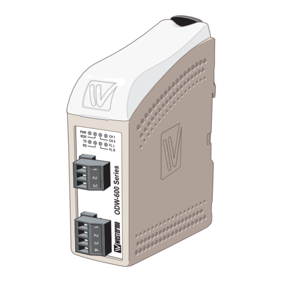
- Page 14 Location of Interface ports, LED’s and DIP-switches DIP-switches accessible under lid (for details see page 16-18) LED Indicators (for details see page 5) Status screw terminal Position Direction Description Product marking Contact with C when fibre opti- cal links are in operation Common Open (no con-...
- Page 15 LED indicators Status Description In service (power) Power Flashing Fault condition Out of service Not used CH 2 Not used CH 1 Fibre link at port CH 1 in operation. Data can be transmitted Fibre link at port CH 1 out of operation Flashing Receive accepted data on the serial port.
- Page 16 Configuration All needed configurations and parameter settings are done by the DIP-switches, located under the top lid. DIP-switch settings Before DIP-switch settings: Prevent damage to internal electronics from electrostatic discharges (ESD) by discharging your body to a grounding point (e.g. use of wrist strap) Note: Disconnect power before DIP-switch settings.
- Page 17 S1 DIP-switch 9 bits data format 11 bits data format 1 2 3 4 5 6 7 8 1 2 3 4 5 6 7 8 10 bits data format 12 bits data format 1 2 3 4 5 6 7 8 1 2 3 4 5 6 7 8 S2 DIP-switch Set status port at local fibre link...
- Page 18 Synchronous mode ODW-630-F1 RS-485 transmitter on-time after last data transition Transmitter Transmitter SW:1 SW:2 SW:1 SW:2 1.6 ms 2.6 µs 1 2 3 4 5 6 7 8 1 2 3 4 5 6 7 8 1 2 3 4 5 6 7 8 1 2 3 4 5 6 7 8 416 µs...
- Page 19 See diagrams for details of how this is done with RS-485 2-wire and 4-wire. R– T– R– R+ T– T+ R– T– R– R+ T– T+ ODW-630-F1 =Termination Slave unit Slave unit Slave unit T/R+ T/R– Max 0.3 metre T/R–...
- Page 20 Mounting This unit should be mounted on 35 mm DIN-rail, which is horizontally mounted inside an apparatus cabinet, or similar. Snap on mounting, see figure. Cooling 10 mm * (0.4 inches) This unit uses convection cooling. To avoid obstructing the air- 25 mm flow around the unit, use the following spacing rules.
- Page 21 LED. … Connect the serial cables from PLC master and slave to respective ODW-630-F1s. … Frames from PLC master that are correctly received in the ODW-630-F1 will be indicated by flashing TD LED. … Frames that are received via the fibre link will be transmitted to the PLC slave and indicated by flashing RD LED.
- Page 22 Flashing of the TD LED indicates that a start-bit has been identified. The definition of positive and negative T/R+, T/R– and R+, R– can differ between this ODW-630-F1 and other units so it can be helpful to reverse the connection of + and –. 6651-22641...
- Page 23 6651-22641...
- Page 24 Westermo • SE-640 40 Stora Sundby, Sweden Tel +46 16 42 80 00 Fax +46 16 42 80 01 E-mail: info@westermo.com www.westermo.com REV. B 6651-22641 2019-01 Westermo Network Technologies AB, Sweden...
Need help?
Do you have a question about the ODW-630-F1 and is the answer not in the manual?
Questions and answers