
Related Manuals for Westermo ODW-720-F2


Summary of Contents for Westermo ODW-720-F2
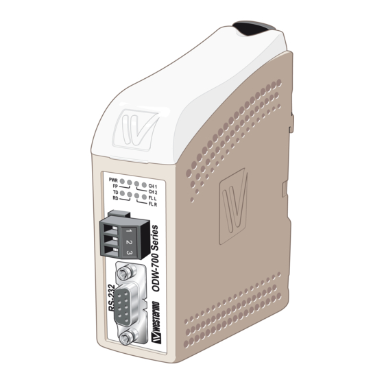
- Page 1 User Guide 6651-2231 ODW-720-F2 Fibre Optic Modem Industrial Converter RS-232 to Fibre Optic Link. Repeater, line and redundant ring www.westermo.com...
-
Page 2: Legal Information
Under no circumstances shall Westermo be responsible for any loss of data or income or any special, incidental, and consequential or indirect damages howsoever caused. -
Page 3: Before Installation
Do not use or store the unit in dusty, dirty areas. Connectors as well as other mechanical parts may be damaged. If the unit is not working properly, contact the place of purchase, nearest Westermo distributor office, or Westermo Tech support. -
Page 4: Maintenance
EN 60950-1, IT equipment** ATEX** EN 60079-0 and EN 60079-15 * Applicable for ODW-720-F2 only ** Applicable for ODW-720-F2 Ex only FCC Part 15.105 This equipment has been tested and found to comply with the limits for a Class A Notice: digital device, pursuant to Part 15 of the FCC Rules. - Page 5 ATEX Information (Applicable for ODW-720-F2 Ex only) General This unit is intended for use in Zone 2 hazardous location only. Marking II 3 G Ex nA IIC T4 Gc SPECIAL CONDITION WARNING – DO NOT SEPARATE WHEN ENERGIZED Indicate that this unit complies with relevant European standards that are harmonised with the 94/9/EC Directive (ATEX).
-
Page 6: Safety Control Drawing
Ratings Power (12 – 48) VDC; 400 mA –40ºC ≤ Ta ≤ +60ºC Ambient temperature Ingress protection (IP) IP21 Maximum surface temperatur 135ºC (temperature class T4) Safety Control Drawing Degree of protection IP 21 Ambient temperature –40°C to +60°C Minimum 25 mm above / below Installation spacing Minimum 10 mm left / right Direction relative this unit! -
Page 7: Special Condition For Safe Use
SPECIAL CONDITION FOR SAFE USE Ambient temperature: This unit is designed for use in extreme ambient temperature conditions as follows: –40 ºC ≤ Ta ≤ +60 ºC Installation in an apparatus cabinet: This unit requires installation in an Ex certified apparatus cabinet suitable for the area of use and providing a degree of protection of at least IP54. -
Page 8: Declaration Of Conformity
Declaration of Conformity Westermo Teleindustri AB Declaration of conformity The manufacturer Westermo Teleindustri AB SE-640 40 Stora Sundby, Sweden Herewith declares that the product(s) Type of product Model Art no Industrial fiberoptic repeaters/media ODW-700 series 3651-07xx converters ODW-700EX series 3651-37xx is in conformity with the following EC directive(s). -
Page 9: Type Tests And Environmental Conditions
7.5 mm, 5 – 8 Hz 2 g, 8 – 500 Hz Shock IEC 60068-2-27 Operating 15 g, 11 ms Packaging Enclosure, ODW-720-F2 UL 94 PC / ABS Flammability class V-1 Enclosure, Cabelec 6141 ODW-720-F2 EX Dimension W x H x D... -
Page 10: Functional Description
Functional description LED’s Switches POWER Internal Electronics RS -232 ODW-720 STATUS SHIELD CH 1 OVP Over Voltage Protection Fibre transceiver OCP Over Current Protection CH 2 Fibre transceiver Converter serial interface – optical fibre ODW-720 is a fibre optic modem that converts between electrical RS-232 and a fibre optical link. -
Page 11: Interface Specifications
Interface specifications Power Rated voltage ODW-720-F2: 12 to 48 VDC and 24 VAC ODW-720-F2 Ex: 12 to 48 VDC Operating voltage ODW-720-F2: 10 to 60 VDC and 20 to 30 VAC ODW-720-F2 Ex: 10 to 60 VDC Rated current 400 mA @ 12 V... - Page 12 RS-232 Electrical specification EIA RS-232 Data rate 300 bit/s – 250 kbit/s Protocol Asynchronous or synchronous Data format 9 – 12 bits in asynchronous mode Any type in synchronous mode Data retiming Asynchronous mode only Transmission range 15 m Isolation to Status and Power port Connection 9-pin D-sub female (DCE)
- Page 13 Bi-Di Bi-Di FX (Fibre) LC-40 LC-20 Fibre connector LC Simplex LC Simplex Fibre type Singlemode Singlemode 9/125 µm 9/125 µm Wavelength nm, connector 1 Tx 1310, Rx 1550 Tx1310, Rx 1550 Wavelength nm, connector 2 Tx 1550, Rx 1310 Tx 1550, Rx 1310 Transmitter –8/0 dBm –14/8 dBm...
- Page 14 Location of Interface ports, LED’s and DIP-switches ODW-720-F2 DIP-switches accessible under lid (for details see page 16–18) LED Indicators (for details see page 15) Status screw terminal Position Description Product marking Contact with C when fibre optical links are in operation...
-
Page 15: Led Indicators
LED indicators Status Description Power is on. Power Power is off. Focal point Redundant ring member or multidrop unit. CH 2 Fiber link to other unit has been estab- lished at CH 2. Channel 2 link status Flashing Optical power detected but link to other unit has not been established at CH 2. -
Page 16: Dip Switch Settings
DIP-switch settings Before DIP-switch settings: Prevent damage to internal electronics from electrostatic discharges (ESD) by discharging your body to a grounding point (e.g. use of wrist strap) Note: Disconnect power before DIP-switch settings. S1 DIP-switch, asynchronous mode speed selection 300 bit/s 38.4 kbit/s 250 kbit/s 1 2 3 4 5 6 7 8... - Page 17 S1 DIP-switch, synchronous mode time frame selection 1.6 ms 26 µs 2.6 µs 1 2 3 4 5 6 7 8 1 2 3 4 5 6 7 8 1 2 3 4 5 6 7 8 416 µs 13 µs 2.1 µs 1 2 3 4 5 6 7 8 1 2 3 4 5 6 7 8...
-
Page 18: S2 Dip-Switch
S2 DIP-switch CTS always active. Use secondary data channel.* 1 2 3 4 5 6 7 8 1 2 3 4 5 6 7 8 Single channel system redundant Transport RTS to CTS.* ring. E.g. only the primary or secondary channel is used. 1 2 3 4 5 6 7 8 1 2 3 4 5 6 7 8 Dual channel system redundant ring. -
Page 19: Status Port
The ODW-720-F2 power supply is galvanically isolated from all other interfaces. Optical fibre interfaces ODW-720-F2 uses Small Form Factor Pluggable (SFP) transceivers. This means that a wide range of different fibre transceivers and connectors can be used (see page 12–13). - Page 20 Mounting This unit should be mounted on 35 mm DIN-rail, which is horizontally mounted inside an apparatus cabinet, or similar. Snap on mounting, see figure. Cooling 10 mm * (0.4 inches) This unit uses convection cooling. To avoid obstructing the air- 25 mm flow around the unit, use the following spacing rules.
-
Page 21: Referring Documents
Referring documents For detailed information on how to configure the ODW-720-F2 for different applications. Type Description Document number Management Guide Management Guide ODW-720-F2 6651-2235... -
Page 24: Sales Units
Germany Sweden info@westermo.de info.sverige@westermo.se www.westermo.de www.westermo.se For complete contact information, please visit our website at www.westermo.com/contact or scan the QR code with your mobile phone. REV.E 6651-2231 2013-06 Westermo Teleindustri AB, Sweden – A Beijer Electronics Group Company...
Need help?
Do you have a question about the ODW-720-F2 and is the answer not in the manual?
Questions and answers