
Subscribe to Our Youtube Channel
Related Manuals for Westermo ODW-632


Summary of Contents for Westermo ODW-632
- Page 1 User Guide 6650-2252 ODW-632 Fibre Optic Modem Industrial Converter RS-485 to Fibre Optic Link Repeater, line and redundant ring www.westermo.com...
-
Page 2: Legal Information
Under no circumstances shall Westermo be responsible for any loss of data or income or any special, incidental, and consequential or indirect damages howsoever caused. -
Page 3: Before Installation
Do not use or store the unit in dusty, dirty areas. Connectors as well as other mechanical parts may be damaged. If the unit is not working properly, contact the place of purchase, nearest Westermo distributor office, or Westermo Tech support. -
Page 4: Maintenance
Note. Fibre Optic Handling Fibre optic equipment requires careful handling as the fibre components are very sensitive to dust and dirt. If the fibre is disconnected from the modem, the protective plug on the transmitter/receiver must be replaced. The protective plug must be kept on during transportation. -
Page 5: Declaration Of Conformity
Declaration of Conformity Westermo Teleindustri AB Declaration of conformity The manufacturer Westermo Teleindustri AB SE-640 40 Stora Sundby, Sweden Herewith declares that the product(s) Type of product Model Art no Industrial fiberoptic repeaters/media ODW-600 Series 3650-0xxx converters is in conformity with the following EC directive(s). -
Page 6: Type Tests And Environmental Conditions
Type tests and environmental conditions Electromagnetic Compatibility Phenomena Test Description Level EN 61000-4-2 Enclosure contact ± 6 kV Enclosure air ± 8 kV RF field AM modulated IEC 61000-4-3 Enclosure 10 V/m 80% AM (1 kHz), 80 – 800 MHz 20 V/m 80% AM (1 kHz), 800 –... - Page 7 Description This ODW-632 is a fibre optic modem used for redundant ring and multidrop applica- tions. It acts as a converter between a serial port and a fibre optical link. The maximum distance of the fibre link depends on selected transceiver and fibre type. Distance up to 80 km (50 miles) is available.
-
Page 8: Functional Description
ODW-622 in the same link as ODW-632. Repeater – optical fibre links ODW-632 is a fibre optic repeater that repeats received data from one fibre link out to the other link. This is useful e.g. for long distance communication, where electromagnetic interference may occur or when isolation of the electrical network is needed. - Page 9 The repeating of transferred frames is stopped until this transferred slave frame has returned via ring A. • When the “first” ODW-632 unit receives the master frame (the same frame that has been transmitted by this unit), or after a timeout, data conversion at will be allowed again.
- Page 10 • When the ODW-632 unit connected to the PLC slave receives the slave frame (the same frame that has been transmitted by this unit), or after a timeout, data conver- sion at this unit will be allowed again. … Behaviour under faulty conditions •...
- Page 11 The data is transferred via the fibre optic network to the serial ports of all units. If ODW-632 is connected to two optical fibre links (mid unit) converted data will be trans- mitted in both directions, via both CH 1 and CH 2. With only one optical fibre link (end unit) converted data will be transmitted in one direction, via CH 1 only.
-
Page 12: Status Interface
Manchester coded protocol can be transferred with Synchronous mode. Redundant power supply, galvanic isolated (2 kVAC) to other ports ODW-632 should be supplied with safety extra low voltage (SELV). It is designed to operate permanently over a wide input range and provided with two independent inputs, allowing redundancy should either supply fail. - Page 13 • The data exchange between a master and slave via ODW-632 fibre optic link will run from the ODW-632 units connected to a master to the slave and the same way back to the master. The system delay is calculated by summing the following: 1.
- Page 14 • Redundant ring, one data exchange between master and one slave. One a master and 11 slaves with data rate 9600 bit/s dependent mode. 12 ODW-632 units with a total fibre length of 40 km. A data exchange between master and one slave.
-
Page 15: Interface Specifications
Interface specifications Power Rated voltage 12 to 48 VDC 24 VAC Operating voltage 10 to 60 VDC 20 to 30 VAC Rated current 400 mA @ 12 V 250 mA @ 24 V 100 mA @ 48 V Rated frequency DC: –... - Page 16 Optical Power Budget The allowed link length is calculated from the optical power budget (OPB), the available optical power for a fibre-optic link, and the attenuation of the fibre, comprising losses due to in-line connectors, splices, optical switches and a margin for link ageing (typical 1.5 dB for 1300 nm). The worst-case optical power budget (OPB) in dB for a fibre-optic link is determined by the differ- ence between the transmitter’s output optical power (min) and the receiver input sensitivity (max).
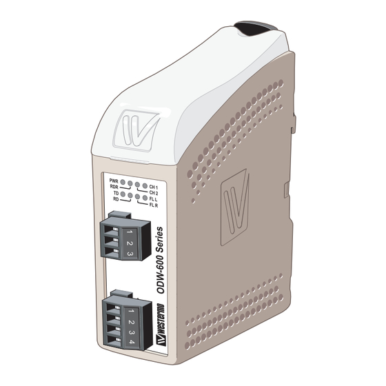
- Page 17 Location of Interface ports, LED’s and DIP-switches ODW-632 LED Indicators(for details see page 18) DIP-switches accessible under lid (for details see page 19-21) Status screw terminal Position Direction* Description Product marking Contact with C when fibre optical links are in opera-...
-
Page 18: Led Indicators
LED indicators Status Description In service (power) Power Flashing Fault condition Out of service Redundant ring mode Multidrop mode CH 2 Fiber link at port CH 2 in operation. Data can be transmitted Fiber link at port CH 2 out of operation CH 1 Fibre link at port CH 1 in operation. - Page 19 Configuration All needed configurations and parameter settings are done by the DIP-switches, located under the top lid of the ODW-632. DIP-switch settings Before DIP-switch settings: Prevent damage to internal electronics from electrostatic discharges (ESD) by discharging your body to a grounding point (e.g. use of wrist strap) Note: Disconnect power before DIP-switch settings.
-
Page 20: S1 Dip-Switch
S1 DIP-switch 9 bits data format 11 bits data format 1 2 3 4 5 6 7 8 1 2 3 4 5 6 7 8 10 bits data format 12 bits data format 1 2 3 4 5 6 7 8 1 2 3 4 5 6 7 8 S2 DIP-switch Multidrop- end unit... - Page 21 Synchronous mode ODW-632 RS-485 transmitter on-time after last data transition Transmitter Transmitter SW:1 SW:2 SW:1 SW:2 1.6 ms 2.6 μs 1 2 3 4 5 6 7 8 1 2 3 4 5 6 7 8 1 2 3 4 5 6 7 8 1 2 3 4 5 6 7 8 416 μs...
- Page 22 See diagrams for details of how this is done with RS-485 2-wire and 4-wire. R– T– R– R+ T– T+ R– T– R– R+ T– T+ ODW-632 =Termination Slave unit Slave unit Slave unit T/R+ T/R– Max 0.3 metre T/R–...
- Page 23 Mounting This unit should be mounted on 35 mm DIN-rail, which is horizontally mounted inside an apparatus cabinet, or similar. Snap on mounting, see figure. Cooling 10 mm * (0.4 inches) This unit uses convection cooling. To avoid obstructing the air- 25 mm flow around the unit, use the following spacing rules.
- Page 24 Connect the power supply to all units. • The Fibre links should be in operation, indicated by active CH 1 and CH 2 LED’s. … Connect each of the slaves to the port of corresponding ODW-632. … Connect the master to the port of one ODW-632.
- Page 25 • The Fibre links should be in operation, indicated by active CH 1 and CH 2 LED’s. … Connect each of the slaves to the serial port of the corresponding ODW-632. … Connect the master to the port of one ODW-632 …...
-
Page 26: Start-Up Guide
Start up guide Note: With Bi-di fibre it is necessary to have one 1310 nm in one end and 1550 nm in the other end. • Bi-di 1310 nm will transmit with 1310 nm and resceive with 1550 nm. • Bi-di 1550 nm will transmitt with 1550 nm and resceive with 1310 nm. Redundant ring with Bi-di transceivers Unit 1 Unit 2... - Page 27 Multidrop with Bi-di transceivers End unit 1 Unit 2 End unit 3 – Bi-di 1550 nm – Bi-di 1310 nm Bi-di 1310 nm Bi-di 1550 nm Hints If the distance is too long, it may be necessary to adjust the timing of the sender of the frame to allow acknowledgement of the received frame, during configuration of the PLC master.
- Page 28 Phone +65 6743 9801 • Fax +65 6745 0670 E-Mail: sales@westermo.co.uk E-Mail: sales@westermo.com.sg Westermo Data Communications GmbH Goethestraße 67, 68753 Waghäusel Tel.: +49(0)7254-95400-0 • Fax.:+49(0)7254-95400-9 E-Mail: info@westermo.de Westermo Teleindustri AB have distributors in several countries, contact us for further information.
Need help?
Do you have a question about the ODW-632 and is the answer not in the manual?
Questions and answers