
Related Manuals for Westermo ODW-710-F1


Summary of Contents for Westermo ODW-710-F1
- Page 1 ODW-710-F1 Fibre Optic Modem Industrial Converter PROFIBUS DP to Fibre Optic Link-. Point to Point applications...
- Page 2 6651-2201...
-
Page 3: General Information
Under no circumstances shall Westermo be responsible for any loss of data or income or any special, incidental, and consequential or indirect damages howsoever caused. -
Page 4: Safety And Regulations
Safety and Regulations Warning signs are provided to prevent personal injury and/or damages to the product. The following levels are used: Level of warning Description Consequence Consequence personal injury material damage Indicates a potentially Possible death or Major damage to the hazardous situation major injury product... - Page 5 WARNING - PROTECTIVE FUSE It must be possible to disconnect manually from the power supply. Ensure compliance to national installation regulations. Replacing the internal fuse must only be performed by Westermo qualified personell. CAUTION - CLASS 1 LASER PRODUCT Do not look directly into a fibre optical port or any connected fibre, although the product is designed to meet the Class 1 Laser regulations and complies with 21 CFR 1040.10 and 1040.11.
-
Page 6: Care Recommendations
If the product is used in a manner not according to specification, the protection provided by the equipment may be impaired. If the product is not working properly, contact the place of purchase, nearest Westermo distributor office or Westermo technical support. -
Page 7: Declaration Of Conformity
Declaration of Conformity Hereby, Westermo declares that this product is in compliance with applicable EU direc- tives and UK legislations. The full declaration of conformity and other detailed informa- www.westermo.com/support/product-support. tion is available at Agency approvals and standards compliance Type... -
Page 8: Type Tests And Environmental Conditions
Type tests and environmental conditions Electromagnetic Compatibility Phenomena Test Description Level EN 61000-4-2 Enclosure contact ± 6 kV Enclosure air ± 8 kV RF field AM modulated IEC 61000-4-3 Enclosure 10 V/m 80% AM (1 kHz), 80 – 800 MHz 20 V/m 80% AM (1 kHz), 800 –... -
Page 9: Functional Description
Data rate up to 12 Mbit/s ODW-710-F1 converts PROFIBUS DP data using data rates from 9 600 bit/s up to 12 Mbit/s. Retiming of the PROFIBUS DP data ensures that the correct signal form is transmitted from the ODW-710-F1 converter. -
Page 10: Interface Specifications
Interface specifications PROFIBUS DP (RS-485) Electrical specification EIA RS-485 / EN 50 170 Data rate 9 600 bit/s, 19.2, 93.75, 187.5, 500 kbit/s, 1.5, 3, 6 and 12 Mbit/s Data format 8 data bits, even parity, 1 stop bit, 11 bits total Protocol PROFIBUS DP / EN 50170 Data Rate detection... - Page 11 PROFIBUS DP (RS-485) Electrical specification EIA RS-485 / EN 50 170 Data rate 9 600 bit/s, 19.2, 93.75, 187.5, 500 kbit/s, 1.5, 3, 6 and 12 Mbit/s Data format 8 data bits, even parity, 1 stop bit, 11 bits total Protocol PROFIBUS DP / EN 50170 Data Rate detection...
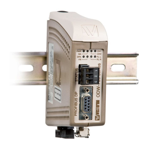
- Page 12 Location of Interface ports, LED’s and DIP-switches ODW-710-F1 LED Indicators DIP-switches accessible under lid Status screw terminal Position Description Product marking Contact with C when fibre optical links are in operation Common Open (no contact with C) when fibre optical links are...
-
Page 13: Led Indicators
LED Indicators Status Description Power is on. Power Power is off. Data rate has been identified and Bus active data frames are being received on the electrical or optical interface. Data rate has not been identified. CH 2 Not used CH 1 Fibre link to other unit has been established at CH 1. -
Page 14: Dip Switch Settings
20 seconds interruption in receiving Only one focal point allowed frames, until inactive BA in a ring. N/A for ODW-710-F1 1 2 3 4 5 6 7 8 1 2 3 4 5 6 7 8 65535 t bit interruption in receiving * See section “About the automatic data rate detection”... -
Page 15: Dip-Switch Description
Description DIP-switch DIP-switch 1 faulty frame before data rate seen as unidentified*. S1: No extended retry limit. 1 2 3 4 5 6 7 8 1 2 3 4 5 6 7 8 2 faulty frames before data rate seen as unidentified*. S1: No extended retry limit. -
Page 16: Start-Up Guide
LED. … The point to point application is up and running. Note: In an ODW-710-F1 fibre optic link there will be some additional processing delays that do not exist in an electrical bus. It is possible that the PROFIBUS application must be adjusted to accommodate for this delay. See “Calculating system processing delay”... - Page 17 LED), data bits are retimed according to the determined rate and sent out on the optical fibre at CH 1. The ODW-710-F1 slave unit receives data at optical fibre CH 1 (as indicated by the FR LED), data rate is automatically detected (as indicated by the BA LED) and data is sent out on the electrical port.
- Page 18 Slave If one fiber in the optical fibre pair fails, all cummunication with will be lost and the FL R LED’s will turn on. The ODW-710-F1 that is still sensing optical power will indicate this by flashing the CH1 LED.
- Page 19 ODW-710-F1. The signal processing delay is dependent on the data rate, and the fibre delay is dependent on the total length of the optical fibre. The additional time resulting from the optical fibre and ODW-710-F1 is the Overall system delay.
-
Page 20: Profibus Dp Interface
About the interfaces Power The power terminal has two independent inputs, +VA and +VB, allowing redundant power input. The ODW-710-F1 power supply is galvanically isolated from all other inter- faces. Optical fibre interfaces ODW-710-F1 uses Small Form Factor Pluggable (SFP) transceivers. This means that a wide range of different fibre transceivers and connectors can be used. - Page 21 About the automatic data rate detection ODW-710-F1 automatically detects the data rate by monitoring incoming PROFIBUS data frames on both the electrical and optical interfaces. When the data rate has been established the BA LED will go active. If no data frames are transmitted for a period of time the automatic data rate detection will restart and the BA LED will go inactive.
- Page 22 Mounting This unit should be mounted on 35 mm DIN-rail, which is horizontally mounted inside an apparatus cabinet, or similar. Snap on mounting, see figure. Cooling 10 mm * (0.4 inches) This unit uses convection cooling. To avoid obstructing the air- 25 mm flow around the unit, use the following spacing rules.
- Page 23 6651-2201...
- Page 24 Westermo • SE-640 40 Stora Sundby, Sweden Tel +46 16 42 80 00 Fax +46 16 42 80 01 E-mail: info@westermo.com www.westermo.com REV. M 6651-2201 2021-05 Westermo Network Technologies AB, Sweden...
Need help?
Do you have a question about the ODW-710-F1 and is the answer not in the manual?
Questions and answers