
Subscribe to Our Youtube Channel
Related Manuals for Westermo ODW-610-F2


Summary of Contents for Westermo ODW-610-F2
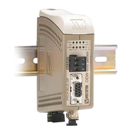
- Page 1 ODW-610-F2 Fibre Optic Modem Industrial Converter PROFIBUS DP to Fibre Optic Link Repeater, line and redundant ring...
- Page 2 6651-22611...
-
Page 3: General Information
Under no circumstances shall Westermo be responsible for any loss of data or income or any special, incidental, and consequential or indirect damages howsoever caused. -
Page 4: Before Installation
Do not use or store the unit in dusty, dirty areas, connectors as well as other mechanical part may be damaged. If the unit is not working properly, contact the place of purchase, nearest Westermo distributor office or Westermo Tech support. -
Page 5: Maintenance
Note. Fibre Optic Handling Fibre optic equipment needs special treatment. It is very sensitive to dust and dirt. If the fibre will be disconnected from the modem the protective hood on the transmitter/ receiver must be connected. The protective hood must be kept on during transportation. The fibre optic cable must also be handle the same way. -
Page 6: Simplified Eu Declaration Of Conformity
Simplified EU declaration of conformity Hereby, Westermo declares that the equipment is in compliance with EU directives. The full EU declaration of conformity and other detailed information are available at the respective product page at www.westermo.com. Agency approvals and standards compliance... -
Page 7: Type Tests And Environmental Conditions
Type tests and environmental conditions Electromagnetic Compatibility Phenomena Test Description Level EN 61000-4-2 Enclosure contact ± 6 kV Enclosure air ± 8 kV RF field AM modulated IEC 61000-4-3 Enclosure 10 V/m 80% AM (1 kHz), 80 – 800 MHz 20 V/m 80% AM (1 kHz), 800 –... -
Page 8: Functional Description
Repeater – optical fibre links ODW-610-F2 is a fibre optic repeater that repeats received data from one fibre link out to the other link. This is useful e.g. for long distance communication, where electromag- netic interference may occur or when isolation of the electrical network is needed. The maximum optical fibre distance depends on selected fibre transceiver and fibre type. - Page 9 Redundant ring via fibre optical network Under normal operation the PROFIBUS DP data is sent over ring A. Should a fault be detected on the fibre ring then the PROFIBUS DP data will be carried on rings A and B. Ring A Ring A Ring A...
- Page 10 The electrical PROFIBUS DP network is transferred via the fibre optic network to the electrical ports of all units. If ODW-610-F2 is connected to two optical fibre links (mid unit) converted data will be transmitted in both directions, via both CH 1 and CH 2.
- Page 11 Redundant power supply, galvanic isolated (2 kVAC) to other ports ODW-610-F2 should be supplied with safety extra low voltage (SELV). It is designed to operate permanently over a wide input range and provided with two independent inputs, allowing redundancy should either supply fail.
- Page 12 ODW-610-F2. The signal processing delay is dependent on the data rate, and the fibre delay is dependent on the total length of the optical fibre.
- Page 13 • Redundant ring, one data exchange between master and one slave. One PROFIBUS DP master and 11 slaves with data rate 1.5 Mbit/s. 12 ODW-610-F2 units with a total fibre length of 40 km. A data exchange between master and one slave.
-
Page 14: Interface Specifications
Interface specifications Power Rated voltage 12 to 48 VDC 24 VAC Operating voltage 10 to 60 VDC 20 to 30 VAC Rated current 400 mA @ 12 VDC 200 mA @ 24 VDC 100 mA @ 48 VDC Rated frequency Inrush current I 0.2 A Startup current*... -
Page 15: Optical Power Budget
FX (Fibre) SM-LC80 SM-LC40 SM-LC15 MM-LC2 Fibre connector LC duplex LC duplex LC duplex LC duplex Fibre type Singlemode Singlemode Singlemode Multimode 9/125 µm 9/125 µm 9/125 µm 62.5/125 and 50/125 µm Wavelength 1550 nm 1310 nm 1310 nm 1310 nm Transmitter –5/0 dBm –5/0 dBm... - Page 16 Connections DIP-switches accessible under lid (for details see page 17-18) LED Indicators (for details see page 16) Status screw terminal 3-position Direction Description No. 1 Contact with C when link is in operation FX(Fibre) (for details No. 2 Common see page 14) No.
-
Page 17: Led Indicators
LED Indicators Status Description In service (power). Power Flashing Fault condition. Out of service. PROFIBUS DP in operation. Bus active Received data frame with detected data rate on the electrical PROFIBUS DP or optical fibre port. Data frame with detected data rate has not been received, or received frames have been interrupted during a time, or a number of consecutive... -
Page 18: Dip Switch Settings
DIP-switch settings Before setting DIP-switches: Prevent damage to internal electronics from electrostatic discharges (ESD) by discharging your body to a grounding point (e.g. use of wrist strap). S1 DIP-switch Set status port at local fibre link error 1 2 3 4 5 6 7 8 S2 DIP-switch Multidrop, end unit application. -
Page 19: Dip-Switch Description
Faulty frame before data rate is seen as unidentified Description DIP-switch DIP-switch 1 faulty frame before data rate is seen as unidentified. S1: No extended retry limit. 1 2 3 4 5 6 7 8 1 2 3 4 5 6 7 8 2 faulty frame before data rate is seen as unidentified. - Page 20 Mounting This unit should be mounted on 35 mm DIN-rail, which is horizontally mounted inside an apparatus cabinet, or similar. Snap on mounting, see figure. Cooling 10 mm * (0.4 inches) This unit uses convection cooling. To avoid obstructing the air- 25 mm flow around the unit, use the following spacing rules.
-
Page 21: Start-Up Guide
… Connect each of the PROFIBUS DP slaves to PROFIBUS DP port of corresponding ODW-610-F2. … Connect PROFIBUS DP master to PROFIBUS DP port of one ODW-610-F2. • The PROFIBUS DP will be in operation and the data rate should have been identified, indicated by BA LED. - Page 22 … Connect each of the PROFIBUS DP slaves to the PROFIBUS DP port of the corresponding ODW-610-F2. … Connect PROFIBUS DP master to the PROFIBUS DP port of one ODW-610-F2 • The PROFIBUS DP will be in operation and the data rate should have been identified, indicated by BA LED.
- Page 23 Hints If the fibre distance is long it may be necessary to adjust the bus parameter Slot time, the monitoring time (t bit ) of the sender of frame for acknowledgement of recipient and the TSDR Station Delay of Responders, at configuration of the PROFIBUS DP master. If the time between transferred PROFIBUS DP frames is long, it may be necessary to allow a longer time of interruption in receiving frames, using DIP-switches.
- Page 24 Westermo • SE-640 40 Stora Sundby, Sweden Tel +46 16 42 80 00 Fax +46 16 42 80 01 E-mail: info@westermo.com www.westermo.com REV. B 6651-22611 2019-01 Westermo Network Technologies AB, Sweden...
Need help?
Do you have a question about the ODW-610-F2 and is the answer not in the manual?
Questions and answers