Table of Contents
Advertisement
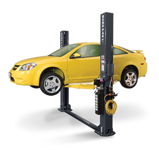
INSTALLATION AND OPERATION MANUAL
9,000 POUND CAPACITY
SURFACE MOUNTED
TWO-POST LIFTS
MODELS:
XPR-9D
RECEIVING
The shipment should be thoroughly inspected as soon as it
is received. The signed Bill of Lading is acknowledgement
by the shipping carrier as receipt of this product as listed
in your invoice as being in a good condition of shipment. If
any of these goods listed on this Bill of Lading are missing
or damaged, do not accept goods until the shipping carrier
makes a notation on the freight bill of the missing or dam-
aged goods. Do this for your own protection.
IMPORTANT SAFETY INSTRUCTIONS
SAVE THESE INSTRUCTIONS
PLEASE READ THE ENTIRE CONTENTS OF THIS MANUAL PRIOR TO
INSTALLATION
AND
INSTALLATION AND OPERATION YOU AGREE THAT YOU FULLY
UNDERSTAND AND COMPREHEND THE FULL CONTENTS OF THIS MANUAL.
FORWARD THIS MANUAL TO ALL OPERATORS. FAILURE TO OPER-
ATE THIS EQUIPMENT AS DIRECTED MAY CAUSE INJURY OR DEATH.
BE SAFE
Your new lift was designed and built with safety in mind.
However, your overall safety can be increased with proper
training and thoughtful operation on the part of the operator.
DO NOT operate or repair this equipment without reading
this manual and the important safety instructions shown
inside. Keep this operation manual near the lift at all times.
Make sure that ALL USERS read and understand this
manual.
1
OPERATION.
BY
PROCEEDING
Santa Paula, CA. 93060, USA
WITH
LIFT
MAN REV A 1-10-11
P/N 5900046
1645 Lemonwood Dr.
Toll Free 1-800-253-2363
Tel: 1-805-933-9970
Fax: 1-805-933-9160
wwwbendpak.com
Advertisement
Table of Contents

Subscribe to Our Youtube Channel
Related Manuals for BendPak XPR-9D Series


Summary of Contents for BendPak XPR-9D Series
- Page 1 IMPORTANT SAFETY INSTRUCTIONS SAVE THESE INSTRUCTIONS PLEASE READ THE ENTIRE CONTENTS OF THIS MANUAL PRIOR TO INSTALLATION OPERATION. PROCEEDING WITH LIFT INSTALLATION AND OPERATION YOU AGREE THAT YOU FULLY UNDERSTAND AND COMPREHEND THE FULL CONTENTS OF THIS MANUAL. FORWARD THIS MANUAL TO ALL OPERATORS. FAILURE TO OPER- ATE THIS EQUIPMENT AS DIRECTED MAY CAUSE INJURY OR DEATH.
-
Page 2: Warranty / Serial Number Information
BendPak Inc. will pay labor costs for the fi rst 12 months only on parts returned as previously described. -
Page 3: Definitions Of Hazard Levels
RECEIPT. Support claim with copies of the Bill of ading, freight bill, invoice, and photographs, if available. BendPak’s willingness to assist in helping you process your claim does not make BendPak responsible for collection of claims or WARNING ! replacement of lost or damaged materials. -
Page 4: Table Of Contents
TABLE OF CONTENTS Contents Page No. Warranty / Serial Number Information ............. . 2 Defi nitions of Hazard Levels . -
Page 5: Installer/Operator Agreement/ Protective Equipment
Shop aprons or shop coats may also be worn, however or damage to property. loose-fi tting clothing should be avoided. I understand that BendPak lifts are designed to be Tight-fi tting leather gloves are recommended to protect installed in indoor locations only. Failure to follow instal- the technician’s hands when handling parts. -
Page 6: Introduction
INTRODUCTION 1. Carefully remove the crating and packing 2. Check the voltage, phase, and proper amperage materials. CAUTION! Be careful when cutting steel requirements for the motor shown on the motor plate. banding material as items may become loose and fall Electrical work should be performed only by a certifi ed causing personal harm or injury. -
Page 7: Tools Required
28 DAYS. IMPORTANT NOTE BendPak lifts are supplied with installation instructions and concrete fasteners meeting the criteria as prescribed by the American National Standard "Automotive Lifts - Safety Requirements for Construction, Testing, and Validation" ANSI/ALI ALCTV-2006. Lift buyers are responsible for any special regional structural and/or seismic anchoring requirements specifi ed... -
Page 8: Assembly View / Description Of Parts
When removing the lift from shipping angles, pay close attention as the posts can slide and can cause injury. Prior to removing the bolts make sure the posts are held securely by a fork lift or some other heavy lifting device. PARTS INVENTORY Be sure to take a complete inventory of parts prior to beginning installation. -
Page 9: Step 3 / Post Preparation
STEP 3 (Post Preparation) NOTE FOR XPR-9D MODELS: COMPLETE THE FOLLOWING PRIOR TO RAISING THE COLUMNS FOR NARROW CONFIGURATION USE THE BUTTON LOCATED AT 12” ABOVE CABLE END. FOR WIDE CONFIGURATION USE THE BUTTON NOTE: LOCATED ON THE END OF THE CABLE. DETERMINE DESIRED LOCATION AND WIDTH LAYOUT BEFORE RAISING COLUMNS. -
Page 10: Step 4 / Site Layout / Floor Plan
Fig 3.5 OPTIONAL SHEAVE COVER INSTALLATION INSTRUCTIONS Threaded Sheave end of cable Sheave Cover Sheave routed down through For Narrow confi guration, carriage lock cable towards Sheave Hex Head button into fi rst opposite Bracket Bolt post button position into Lock Plate inside of car- riage Fig 3.6... -
Page 11: Clearances
STEP 4 4. Once a location is determined, use a carpenters chalk (Site Layout) line to layout a grid for the post locations. Keep all dimensions square within 1/8” (3mm) or malfunctioning of the lift can occur. 1. Determine which side of the lift will be the approach side. 5. -
Page 12: Step 5 / Installing Power Side Post
NOTE: BENDPAK LIFTS ARE SUPPLIED WITH INSTALLATION INSTRUCTIONS AND CONCRETE FASTENERS MEET- ING THE CRITERIA AS PRESCRIBED BY THE AMERI- CAN NATIONAL STANDARD "AUTOMOTIVE LIFTS - SAFETY REQUIREMENTS FOR CONSTRUCTION, TESTING, AND VALIDATION"... -
Page 13: Step 7 / Mounting The Hydraulic Power Unit
STEP 7 (Mounting the Hydraulic Power Unit) 1. Attach the power unit to the POWER SIDE post. Install the vibration dampener between the power unit and WARNING! the power unit mounting plate on the Power Side post, DO NOT RUN POWER UNIT WITHOUT OIL. DAMAGE TO using four M8 hex head bolts and nuts supplied. - Page 14 Off Side Safety Weldment Route safety cable Torsion over Off Side safety Spring sheave and down towards Floorplate Safety Clevis NOTE: Post cut away for clarity Fig 8.4. Hairpin Safety Cotter Fig 8.5 Cable Safety Fig 8.2 Cable From the Off Side post insert the non-looped end of the safety cable through the hole located to the right of the Off Side safety weldment.
-
Page 15: Step 9 / Installing Hydraulic Lines
7. Pull the slack out the safety cable and keep tension STEP 9 on the cable as nuts are being tightened. Tighten jam (Installing Hydraulic Lines) nuts on either side of the cable keeping the cable cen- NOTE: tered to the hole to secure it into place. (See Fig 8.7) FOR THE WIDE CONFIGURATION, A 13”... -
Page 16: Step 10 / Routing The Equalizer Cables
DANGER ! WARNING ! MAKE SURE THAT THE SAFETY LOCKS ON EACH WHEN ROUTING HYDRAULIC HOSES THROUGH POST ARE FULLY ENGAGED BEFORE ATTEMPTING THE POSTS, ROUTE HOSES THROUGH THE HOSE TO ROUTE EQUALIZER CABLES AND/OR HOSES. CLIPS WELDED ON EACH POST. MAKE SURE THAT CARRIAGES MUST BE EQUAL HEIGHT FROM THE THE HOSE IS CLEAR OF ANY MOVING PARTS. - Page 17 Fig. 10.4 Fig 10.3 Threaded Cable End Threaded cable end comes down from Top Plate sheave and into hole on top of car- From To lift riage plate. base head plate carriage sheave Nylock NOTE: Post cut away for clarity NOTE: Post cut away for clarity Insert the threaded end of the cable through the hole on top of the carriage.
-
Page 18: Step 11 / Installing Power Unit Hose Assembly And Power Side Safety Cover
STEP 11 (Installing power unit hose assembly and Power Side safety cover) Lift Head Lift Head After safeties have been adjusted and checked for proper operation, install and tighten Power Side safety Lift Head cover and Off Side safety cover mounting screws. (See Fig. - Page 19 Fig. 12.4 Fig. 12.6 Ensure that the arms do not move when a force of approximately 100 pounds or less is applied laterally to LEFT RIGHT the fully extended arms. 5. Loosen the arm restraint gear bolts and adjust the 9.
-
Page 21: Carriage Stop Bolt Installation Warning
CARRIAGE STOP BOLT INSTALLATION WARNING WARNING! YOU MUST RE-INSTALL TOP CARRIAGE-STOP BOLT (SHOWN BELOW). TIGHTEN CARRIAGE-STOP BOLT TO 2-3 FT.-LBS. OF TORQUE UPON FINAL INSTALLATION INSPECTION. THESE INSTRUCTIONS MUST BE FOLLOWED TO ENSURE PROPER INSTALLATION AND OPERATION OF YOUR LIFT. FAILURE TO COMPLY WITH THESE INSTRUCTIONS CAN RESULT IN SERIOUS BODILY INJURY AND/OR DEATH AND/OR VOID PRODUCT WARRANTY. -
Page 22: Safety Label Placement Guidelines
TWO-POST LIFT POWER SIDE POST SAFETY LABEL PLACEMENT GUIDELINES WARNING! THESE ANSI/ALI ALCTV-2006 MANDATED SAFETY LABELS ARE PROVIDED FOR THIS PRODUCT FOR THE PROTECTION OF THE OPERATOR AND ANY PERSON(S) WORKING NEAR THE LIFT. THE SAFETY STICKERS MUST BE INSTALLED AS PER THE INSTRUCTIONS BELOW, PRIOR TO THE COMPLETION OF INSTALLATION. FAILURE TO PROPERLY INSTALL WARNING LABELS COULD FAIL TO WARN AND LEAD TO SERIOUS PERSONAL INJURY OR DEATH TO OPERATOR OR BYSTANDER OR DAMAGE TO PROPERTY. -
Page 23: Step 13 / Power Unit Connection
DANGER! DO NOT PERFORM ANY MAINTENANCE OR INSTALLATION OF ANY COMPONENTS WITH OUT FIRST ENSURING THAT ELECTRICAL POWER HAS BEEN DISCONNECTED AT THE SOURCE OR PANEL AND CANNOT BE RE-ENERGIZED UNTIL ALL MAINTENANCE AND/OR INSTALLATION PROCEDURES ARE COMPLETED. IMPORTANT POWER-UNIT INSTALLATION NOTES DO NOT run power unit without oil. -
Page 24: Step 14 / Lift Start Up / Final Adjustments
STEP 13 STEP 14 (Power Unit Connection) (Lift Start Up / Final Adjustments) 1. Have a certifi ed electrician run the power supply to motor. Refer to the data plate found on the motor for proper power supply and wire size. CAUTION! DURING THE START-UP PROCEDURE, OBSERVE ALL OPERATING COMPONENTS AND CHECK... -
Page 25: Post Installation Checklist
POST-INSTALLATION CHECK-OFF STEP 16 (Bleeding the Cylinders) Posts properly shimmed and stable Anchor bolts tightened Pivot / sheave pins properly attached Carriage stop bolts torqued to 2-3 ft-lb DANGER! Electric power supply confi rmed THE LIFT WILL MOVE DOWN WHEN BLEEDING Cables adjusted properly MAKE SURE ALL EQUIPMENT, PERSONNEL ,HANDS ... -
Page 26: Optional Equipment Installation
OPTIONAL EQUIPMENT INSTALLATION... - Page 27 1. Install the Foot Guards to the outside of the 4 Lift Arm Assemblies. Tighten the Hex Head Bolts. (See Fig 1-2) Footguards Hex Head Bolt Footguards Footguards OPTIONAL CRADLE AND SCREW PAD ADAPTERS SCREW PAD ADAPTER FRAME CRADLE PAD ADAPTER Optional Equipment available through your Authorized BendPak Dealer.
-
Page 28: Step 17 / Operation/ Maintenance
• ALWAYS keep area around lift free of tools, debris, or if it has broken or damaged parts. Use only qualifi ed lift grease and oil. service personnel and genuine BendPak parts to make repairs. • NEVER overload lift. Capacity of lift is shown on nameplate affixed to the lift. - Page 29 LIFT OPERATION SAFETY (CONT’D) • ALWAYS load vehicle on lift carefully. Position the lift adapters to contact at the vehicle manufacturer’s recommended lift points. Raise lift until adapters contact vehicle. Check adapters for secure contact with vehicle. Raise lift to desired working height. (See Fig.17.1) WARNING! WHEN LOWERING THE LIFT PAY CAREFUL ATTEN- TION THAT ALL PERSONNEL AND OBJECTS ARE...
- Page 30 LIFT OPERATION SAFETY (CONT’D) TYPICAL LIFTING POINTS Fig. 17.2 Never exceed 9” of lift adapter height by any combination of adapters. 9" MAXIMUM Failure to comply can result in serious damage, personal injury, or death. Fig. 17.3 WARNING! MANY SPECIALTY OR MODIFIED VEHICLES CAN- NOT BE RAISED ON A TWO-POST FRAME ENGAG- ING LIFT.
- Page 31 LIFT OPERATION SAFETY (CONT’D) 10. Continue to raise to desired height only if vehicle is TO LOWER THE LIFT secure on lift. 11. DO NOT go near or under a raised vehicle if all four adapters are not in secure contact with vehicle at vehicle WARNING! manufacturer’s recommended lift points.
- Page 32 • Daily: Check cables and sheaves for wear. Replace refi ll if required per lift installation instructions. worn parts as required with genuine BendPak parts. • Replace all caution, warning or safety related decals on the lift if unable to read or missing. Reorder labels •...
- Page 33 TO RAISE LIFT Read operating and safety manuals before using lift. Always lift a vehicle according to the manufacturers recommended lifting points. Position vehicle between posts. Adjust swing arms so that the vehicle is positioned with the center of gravity midway between pads. ...
- Page 34 WIRE ROPE INSPECTION AND MAINTENANCE Lifting cables should be replaced every three - fi ve years or when visible signs of damage are apparent. DO NOT USE LIFT WITH DEFECTIVE / WORN CABLES. Lifting cables should be maintained in a well-lubricated condition at all times. Wire rope is only fully protected when each wire strand is lubricated both internal and external.
- Page 37 Safe Lift Operation Automotive and truck lifts are critical to the operation and profi tability of your business. The safe use of this and other lifts in your shop is critical in preventing employee injuries and damage to customer’s vehicles. By operating lifts safely you can insure that your shop is profi table, productive and safe.
- Page 38 DO NOT leave the controls while the lift is still in motion. DO NOT stand directly in front of the vehicle or in the bay when vehicle is being loaded or driven into position. DO NOT go near vehicle or attempt to work on the vehicle when being raised or lowered. ...
-
Page 39: Troubleshooting Guide
8. Oil seal damaged or cocked ......Replace oil seal around pump shaft. 9. See Installation Manual ......Contact BendPak Customer Support. - Page 40 INSTRUCTION See Installation Manual ......Contact BendPak Customer Support. Replace with new part ......Replace with new part.
- Page 41 6. Return unit for repair ....... Return unit for repair. 7. See Installation Manual ......Contact BendPak Customer Support.
-
Page 42: Maintenance Records
MAINTENANCE RECORDS ____________________________________________________________________ ____________________________________________________________________ ____________________________________________________________________ ____________________________________________________________________ ____________________________________________________________________ ____________________________________________________________________ ____________________________________________________________________ ____________________________________________________________________ ____________________________________________________________________ ____________________________________________________________________ ____________________________________________________________________ ____________________________________________________________________ ____________________________________________________________________ ____________________________________________________________________ ____________________________________________________________________ ____________________________________________________________________ ____________________________________________________________________ ____________________________________________________________________ ____________________________________________________________________ ____________________________________________________________________... - Page 43 MAINTENANCE RECORDS ____________________________________________________________________ ____________________________________________________________________ ____________________________________________________________________ ____________________________________________________________________ ____________________________________________________________________ ____________________________________________________________________ ____________________________________________________________________ ____________________________________________________________________ ____________________________________________________________________ ____________________________________________________________________ ____________________________________________________________________ ____________________________________________________________________ ____________________________________________________________________ ____________________________________________________________________ ____________________________________________________________________ ____________________________________________________________________ ____________________________________________________________________ ____________________________________________________________________ ____________________________________________________________________ ____________________________________________________________________...
- Page 48 For Parts Or Service Contact: BendPak Inc. / Ranger Products 1645 Lemonwood Dr. Santa Paula, CA. 93060 Tel: 1-805-933-9970 Toll Free: 1-800-253-2363 Fax: 1-805-933-9160 www.bendpak.com www.rangerproducts.com p/n 5900046...
Need help?
Do you have a question about the XPR-9D Series and is the answer not in the manual?
Questions and answers