Table of Contents
Advertisement
Quick Links
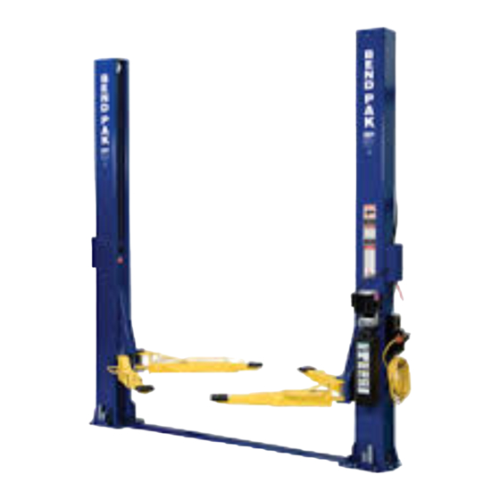
INSTALLATION AND OPERATION MANUAL
9,000 POUND CAPACITY
SURFACE MOUNTED
TWO-POST LIFTS
MODELS:
XPR-9F
XPR-9FX
VERSION A
SHIPPING DAMAGE CLAIMS
When this equipment is shipped, title passes to the
purchaser upon receipt from the carrier. Consequently,
claims for the material damaged in shipment must be
made by the purchaser against the transportation
company at the time shipment is received.
PLEASE READ THE ENTIRE CONTENTS OF THIS MANUAL PRIOR TO
INSTALLATION AND OPERATION. BY PROCEEDING YOU AGREE THAT
YOU FULLY UNDERSTAND AND COMPREHEND THE FULL CONTENTS OF
THIS MANUAL. FORWARD THIS MANUAL TO ALL OPERATORS. FAILURE TO
OPERATE THIS EQUIPMENT AS DIRECTED MAY CAUSE INJURY OR DEATH.
BE SAFE
Your new lift was designed and built with safety in mind.
However, your overall safety can be increased by proper
training and thoughtful operation on the part of the operator.
DO NOT operate or repair this equipment without reading this
manual and the important safety instructions shown inside.
Keep this operation manual near the
machine at all times. Make sure that
ALL USERS read this manual.
1645 Lemonwood Dr.
Santa Paula, CA. 93060, USA
Toll Free: 1-800-253-2363
REV C 06.-18-09
Tel: 1-805-933-9970
Fax: 1-805-933-9160
wwwbendpak.com
Advertisement
Table of Contents

Related Manuals for BendPak XPR-9F


Summary of Contents for BendPak XPR-9F
- Page 1 REV C 06.-18-09 INSTALLATION AND OPERATION MANUAL 9,000 POUND CAPACITY SURFACE MOUNTED TWO-POST LIFTS MODELS: XPR-9F XPR-9FX VERSION A Keep this operation manual near the machine at all times. Make sure that ALL USERS read this manual. SHIPPING DAMAGE CLAIMS BE SAFE Your new lift was designed and built with safety in mind.
-
Page 2: Warranty / Serial Number Information
BendPak Inc. shall repair or replace at their option for the warranty period those parts returned to the factory freight prepaid which prove upon inspection to be defective. BendPak Inc. will pay labor costs for the first 12 months only on parts returned as previously described. -
Page 3: Definitions Of Hazard Levels
Our willingness to practices which may result in minor personal injury, assist in helping you process your claim does not make product or property damage. BendPak responsible for collection of claims or replacement of lost or damaged materials. -
Page 4: Table Of Contents
TABLE OF CONTENTS Contents Page No. Warranty / Serial Number Information ..............2 Definitions of Hazard Levels . -
Page 5: Installers Agreement / Operator Protective Equipment
I understand that Bendpak lifts are designed to be installation and operation activities. installed in indoor locations only. Failure to follow... -
Page 6: Introduction
INTRODUCTION Carefully remove the crating and packing 2. Check the voltage, phase and proper amperage materials. CAUTION! Be careful when cutting steel requirements for the motor shown on the motor plate. banding material as items may become loose and fall Wiring should be performed by a certified electrician causing personal harm or injury. -
Page 7: Tools Required
TOOLS REQUIRED Rotary Hammer Drill or Similar Large Crescent Wrench 3/4” Masonry Bit Large Pipe Wrench Hammer Crow Bar 4 Foot Level Chalk Line Open-End Wrench Set: SAE/Metric Medium Flat Screwdriver Socket And Ratchet Set: SAE/Metric Tape Measure: 25 Foot Minimum Hex-Key / Allen Wrench Set Needle Nose Pliers IMPORTANT NOTICE ! -
Page 8: Assembly View / Description Of Parts
When removing the lift from shipping angles pay close attention as the posts can slide and can cause injury. Prior to removing the bolts make sure the posts are held securely by a fork lift or some other heavy lifting devise. PARTS INVENTORY Be sure to take a complete inventory of parts prior to beginning installation. -
Page 9: Step 3 / Lifting Chain Installation
STEP 3 Connecting the Lifting Chain to the Lift Head (Lifting Chain Installation) 5. Determine the proper orientation of the Chain COMPLETE THE FOLLOWING Connector. The Chain Connector must be installed with the PRIOR TO STANDING UP COLUMNS. Hole for the Chain Master Link offset as shown. (See Fig 3.4) With the Column laying on the Floor, slide the Lift Head Fig 3.4... - Page 10 Install and tighten the Socket Head Cap Screws and Fig 3.10 Nylock Nuts. (See Fig 3.7) Install the Cylinder Chain Roller on to the Cylinder Fig 3.7 Rod. Lay the Cylinder and Roller Assy. into the Column on top of the Chain. Insure that the Cylinder Leveling plug is in Connecting the Lifting Chain to the Post Base place in the base of the Cylinder.
-
Page 11: Step 4 / Preparing The Columns
Slowly lower the Lift Head down to the Base of the Fig 4.2 Column. Guide the Chain and the Cylinder Assembly so as to keep the Chain in line with the Chain Roller. (See Fig. 3.13 ) 2. Install the 90* 3/8” Fitting into the Cylinder port using Fig 3.13 Teflon tape on the pipe threads. - Page 12 4. Connect Tube Fitting Assembly to the 90* 3/8 Fitting that Fig 4.7 was installed into the Cylinder Port, using Teflon tape on the pipe threads. (See Fig. 4.5) Fig 4.5 7. Bolt the Top Plate Assembly to the Column using the M10 Bolts, Washers and Nuts provided in the parts box.
-
Page 13: Floor Plan / Specifications
FLOOR PLAN / LAYOUT Fig 4.1. Model Capacity XPR-9F 3353 mm / 132” 9,000 Lbs. XPR-9FX 3683 mm / 145” 9,000 Lbs. STEP 5 4. After the Column locations are properly marked, use a ( Site Layout ) chalk or crayon to make an outline of the Column on the floor at each location using the Column base plates as a 1. -
Page 14: Step 6 / Installing Powerside Columns
STEP 6 Fig 6.3 (Installing Powerside Column) 1. Before proceeding, double the check measurements and make certain that the bases of each Column are aligned with the chalk line. 2. Using the base plate on the POWERSIDE Column as a guide, drill each anchor hole in the concrete (approximately 4-1/2”... -
Page 15: Step 8 / Mounting Power Unit
STEP 8 (Mounting the Hydraulic Power Unit) 1. Attach the Power Unit to the POWERSIDE COLUMN. DANGER ! install the Vibration Dampener between the Power Unit ALL WIRING MUST BE PERFORMED and the Power Unit Mounting Plate on the Powerside BY A LICENSED ELECTRICIAN. -
Page 16: Step 9 Installing Safeties And Safety Cables
STEP 9 From the Offside Column insert the non looped end of the Safety Cable through the hole located to the right of Installing the Safeties and Safety Cable) the Offside Safety Weldment. (See Fig 9.3) Install Safety Weldments into each respective Fig 9.3 Column. - Page 17 4. Route the Safety Cable through the Base Plate Safety Cable Pulley(s) and across the floor towards the Powerside Column. (See Figs 9.5 & 9.6) Fig 9.5 Fig 9.6. Fig 9.7 8. Operate the Power Side Safety Handle, check for Proper Operation of both Safety Assemblies and adjust Cable tension as required.
-
Page 18: Step 10 / Installing Hydraulic Hoses
STEP 10 Fig 10.2 (Installing Hydraulic Lines) DANGER ! MAKE SURE THAT THE SAFETY LOCKS ON EACH COLUMN ARE FULLY ENGAGED BEFORE ATTEMPTING TO ROUTE EQUALIZER CABLES AND/OR HOSES. CARRIAGES MUST BE EQUAL HEIGHT FROM THE FLOOR BEFORE PROCEEDING. 1. Raise and lock each Carriage approximately 28” above the ground. -
Page 19: Step 11 / Installing Equalizer Cables
NOTE: STEP 11 REFER TO THE DOCUMENTATION THAT CAME Routing the Equalizer Cables) WITH THE POWER UNIT FOR THE LOCATION OF POWER PORT. 8. Remove plug from Power Unit and install the 90* Fitting w/ O-ring into the Power Port on the Power Unit. Use Teflon Tape on the Pipe Fitting side ONLY. - Page 20 Fig. 11.4 DANGER ! MAKE SURE THAT THE SAFETY LOCKS ON EACH COLUMN ARE FULLY ENGAGED BEFORE ATTEMPTING TO ROUTE EQUALIZER CABLES AND/OR HOSES. CARRIAGES MUST BE EQUAL HEIGHT FROM THE FLOOR BEFORE PROCEEDING. NOTE: The Equalizer Pulleys should be removed to assist in the routing of the Equalizer Cables.
-
Page 21: Step 12 / Installing Powerside And Offside Safety Covers
STEP 12 (Installing Powerside and Offside Safety Cover) After Safeties have been adjusted and checked for proper operation, install and tighten Powerside Safety Cover and Offside Safety Cover mounting Bolts. (See Fig. 12.1 and 12.2) Fig. 12.1 THIS SPACE INTENTIONALLY Fig. -
Page 22: Step 13 / Installing Lift Arms
STEP 13 3. Install the Snap Ring into the groove in the Lift Head Pin the under side of the Lift Head. (See Fig. 13.2) (Installing the Lift Arms) 1. Place the appropriate Lift Arm Assy. on the Lift Heads. (See Fig. 13.3) 2. - Page 23 8. Adjust the Gear ring on the Arm as necessary to ensure smooth operation and solid engagement of all four Arm Restraint Pin Assemblies with the Arm Restraint Gear Ring. DANGER! The Arm Restraint Gears must be properly adjusted and confirmation that the gears are engaging properly must be made prior to operating the lift.
- Page 25 You MUST re-install top Carriage-Stop Bolt (shown below) after top beam/plate is installed and secured. Tighten carriage-stop bolt to 2-3 ft.-lbs. of torque upon final installation inspection. These instructions must be followed to insure proper installation and operation of your lift. Failure to comply with these instructions can result in serious bodily injury and or death and or void product warranty.
- Page 26 DANGER! DO NOT PERFORM ANY MAINTENANCE OR INSTALLATION OF ANY COMPONENTS WITH OUT FIRST ENSURING THAT ELECTRICAL POWER HAS BEEN DISCONNECTED AT THE SOURCE OR PANEL AND CANNOT BE RE-ENERGIZED UNTIL ALL MAINTENANCE AND/OR INSTALLATION PROCEDURES ARE COMPLETED. IMPORTANT POWER-UNIT INSTALLATION NOTES DO NOT run power unit with no oil.
-
Page 28: Step 14 / Power Unit Hookup
STEP 15 STEP 14 (Lift Start Up / Final Adjustments) (Power Unit Hook Up) 1. Have a certified electrician run the power supply to motor. Refer to the data plate found on the motor for proper power supply and wire size. CAUTION! DURING THE START-UP PROCEDURE, OBSERVE ALL OPERATING COMPONENTS AND CHECK... - Page 29 POST-INSTALLATION CHECK-OFF NOTE: THERE WILL BE INITIAL STRETCHING OF THE Columns Properly Shimmed And Stable CABLES AND/OR WITH INCREASED LOADS. Anchor Bolts Tightened ADJUST THE CABLES AS OUTLINED ABOVE A Pivot / Sheave Pins Properly Attached WEEK AFTER FIRST USE, THEN EVERY THREE TO Carriage Stop bolts Torqued to 2-3 Ft.- Lbs SIX MONTHS THEREAFTER DEPENDING ON USAGE Electric Power Supply Confirmed...
-
Page 30: Optional Equipment Installation
OPTIONAL EQUIPMENT INSTALLATION... -
Page 31: Step 17 / Operation/ Maintenance
OPTIONAL FOOT GUARD INSTALLATION 1. Install the Foot Guards to the outside of the 4 Lift Arm Assemblies. Tighten the Hex Head Bolts. (See Fig 1-2) OPTIONAL FRAME CRADLE AND SCREW PAD ADAPTERS Optional Equipment available through your Authorized BendPak Dealer. - Page 32 STEP 17 To Lower Lift; 1. Before lowering vehicle, be sure all personnel are (Operation) clear of the lift and surrounding area. Pay careful attention To Raise Lift; to overhead clearances. Insure all tools and equipment 1. Load vehicle onto the lift using Vehicle Lifting Guide have been cleared from under the lift.
- Page 33 TO RAISE LIFT Read operating and Safety manuals before using lift. Always lift a vehicle according to the manufactures recommended lifting points. Position vehicle between columns. Adjust swing arms so that the vehicle is positioned with the center of gravity midway between pads. Use truck adapters as needed.
- Page 34 WIRE ROPE INSPECTION AND MAINTENANCE Lifting cables should be replaced every three - five years or when visible signs of damage are apparent. DO NOT USE LIFT WITH DEFECTIVE / WORN CABLES. Lifting cables should be maintained in a well-lubricated condition at all times. Wire rope is only fully protected when each wire strand is lubricated both internal and external.
- Page 37 Safe Lift Operation Automotive and truck lifts are critical to the operation and profitability of your business. The safe use of this and other lifts in your shop is critical in preventing employee injuries and damage to customer’s vehicles. By operating lifts safely you can insure that your shop is profitable, productive and safe.
- Page 38 DO NOT leave the controls while the lift is still in motion. DO NOT stand directly in front of the vehicle or in the bay when vehicle is being loaded or driven into position. DO NOT go near vehicle or attempt to work on the vehicle when being raised or lowered. REMAIN CLEAR of lift when raising or lowering vehicle.
- Page 39 LIFT WILL NOT RAISE POSSIBLE CAUSE 1. Air in oil, (1,2,8,13) 2. Cylinder binding, (9) 3. Cylinder leaks internally, (9) 4. Motor run backward under pressure, (11) 5. Lowering valve leaks, (3,4,6,10,11) 6. Motor runs backwards, (7,14,11) 7. Pump damaged, (10,11) 8.
- Page 40 MOTOR WILL NOT RUN POSSIBLE CAUSE Fuse blown, (5,2,1,3,4) Limit switch burned out, (1,2,3,4) Microswitch burned out, (1,2,3,4) Motor burned out, (1,2,3,4,6) Voltage to motor incorrect, (2,1,8) REMEDY INSTRUCTION Check for correct voltage ......Compare supply voltage with voltage on motor name tag.
- Page 41 WILL NOT RAISE LOADED LIFT POSSIBLE CAUSE 1. Air in oil, (1,2,3,4) 2. Cylinder binding, (5) 3. Cylinder leaks internally, (5) 4. Lift overloaded, (6,5) 5. Lowering valve leaks, (7,8,1,5,9) 6. Motor runs backwards, (10,12,9) 7. Pump damaged, (5,9) 8. Pump won’t prime, (1,2,3,4,5,11,9) 9.
-
Page 42: Part Number Lists
LIFT WILL NOT STAY UP POSSIBLE CAUSE 1. Air in oil, (1,2,3) 2. Check valve leaks, (6) 3. Cylinders leak internally, (7) 4. Lowering valve leaks, (4,5,1,7,6) 5. Leaking fittings, (8) REMEDY INSTRUCTION 1. Check oil level ........The oil level should be up to the bleed screw in the reservoir with the lift all the way down. - Page 51 MAINTENANCE RECORDS ____________________________________________________________________ ____________________________________________________________________ ____________________________________________________________________ ____________________________________________________________________ ____________________________________________________________________ ____________________________________________________________________ ____________________________________________________________________ ____________________________________________________________________ ____________________________________________________________________ ____________________________________________________________________ ____________________________________________________________________ ____________________________________________________________________ ____________________________________________________________________ ____________________________________________________________________ ____________________________________________________________________ ____________________________________________________________________ ____________________________________________________________________ ____________________________________________________________________ ____________________________________________________________________ ____________________________________________________________________...
- Page 52 For Parts Or Service Contact: BendPak Inc. / Ranger Products 1645 Lemonwood Dr. Santa Paula, CA. 93060 Tel: 1-805-933-9970 Toll Free: 1-800-253-2363 Fax: 1-805-933-9160 www.bendpak.com www.rangerproducts.com...
Need help?
Do you have a question about the XPR-9F and is the answer not in the manual?
Questions and answers