Table of Contents
Advertisement
Quick Links
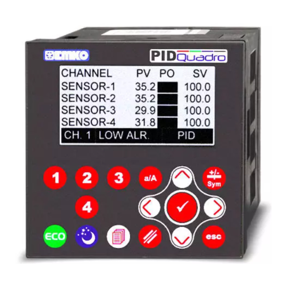
EPLC9600-PID QUADRO 96 x 96 DIN 1/4
4 Channel PID Controller
- 128 x 64 Graphical LCD display
- 4 Thermocouple (J, K, L, R or S type)
- C
onfigurable P, PI, PD and PID control forms
- Auto-Tuning and Self-Tuning (automatic calculations of PID
parameters)
- Relay or (pnp "source") transistor outputs
- Sensor error detection
- Programmable heating and cooling for PID control outputs
- Soft-Start (Ramp action during power on) specification
- ECO and SLEEP mode selection
(mode can be activating automatically according to mode control
parameter which can be adjust for each day of week or via front
panel buttons or via digital inputs.)
- Adjustable temperature offset for each channel
- 3 Different alarm types for each channel
(High, Low and Band Alarms)
- User defined channel labels
- Operating with Real Time Clock (RTC)
- ModBus RTU communication protocol
(RS-232, RS-485 and Ethernet communication)
- Data Logging to USB Flash Memory
- Adjustable data logging time interval
- Password protection for programming mode
sensor inputs
Introduction Manual. ENG EPLC-9600 PID QUADRO V04 11/18
Advertisement
Table of Contents

Related Manuals for EMKO PID QUADRO EPLC9600


Summary of Contents for EMKO PID QUADRO EPLC9600
- Page 1 EPLC9600-PID QUADRO 96 x 96 DIN 1/4 4 Channel PID Controller - 128 x 64 Graphical LCD display - 4 Thermocouple (J, K, L, R or S type) sensor inputs onfigurable P, PI, PD and PID control forms - Auto-Tuning and Self-Tuning (automatic calculations of PID parameters) - Relay or (pnp “source”) transistor outputs - Sensor error detection...
- Page 2 ABOUT INSTRUCTION MANUAL Instruction manual of EPLC9600-PID QUADRO consists of two main sections. Explanation of these sections are below. Also, there are other sections which include order information and technical specifications of the device. All titles and page numbers in instruction manual are in “CONTENTS”...
-
Page 3: Table Of Contents
CONTENTS 1.PREFACE............................Page 1.1 GENERAL SPECIFICATIONS 1.2 ORDERING INFORMATION 1.3 WARRANTY 1.4 MAINTENANCE 2.INSTALLATION............................ Page 2.1 GENERAL DESCRIPTION 2.2 FRONT VIEW AND DIMENSIONS OF EPLC9600-PID QUADRO 2.3 PANEL CUT-OUT 2.4 ENVIRONMENTAL RATINGS 2.5 PANEL MOUNTING 2.6 INSTALLATION FIXING CLAMP 2.7 REMOVING FROM THE PANEL 3.ELECTRICAL WIRING........................ - Page 4 EU DECLARATION OF CONFORMITY Manufacturer’s Name : EMKO ELEKTRONIK A.S. Manufacturer’s Address : DOSAB, Karanfil Sk., No:6, 16369 Bursa, TURKEY The manufacturer hereby declares that the product: Product Name : PID QUADRO (4 Channel PID Controller) Type Number : EPLC9600...
-
Page 5: General Specifications
1.Preface EPLC9600-PID QUADRO series 4 channel PID controller devices are designed for measuring, controlling and logging temperatures of 4 different area. They can be used in many applications with their TC process input, multifunction PID control outputs, alarm outputs, selectable alarm functions, RS-232 / RS-485 / Ethernet / USB communications. Some application fields and applications which they are used are below: Application Fields Applications... -
Page 6: Ordering Information
0°C,1700°C 1.3 Warranty EMKO Elektronik warrants that the equipment delivered is free from defects in material and workmanship. This warranty is provided for a period of two years. The warranty period starts from the delivery date. This warranty is in force if duty and responsibilities which are determined in warranty document and instruction manual performs by the customer completely. -
Page 7: Installation
2.Installation Before beginning installation of this product, please read the instruction manual and warnings below carefully. In package , - One piece unit - Two pieces mounting clamps - One piece instruction manual A visual inspection of this product for possible damage occured during shipment is recommended before installation. -
Page 8: General Description
2.1 General Description Mounting Clamp Panel surface (maximum thickness 15 mm / 0.59 inch) Front Panel IP65 protection NEMA 4X Front View and Dimensions of EPLC9600-PID QUADRO Maximum 15 mm / 0.59 inch 96 mm / 3.78 inch 12 ± 1 mm / 0.47 inch 84 mm / 3.31 inch... -
Page 9: Panel Cut-Out
2.3 Panel Cut-Out 129 mm / 5.08 inch (min) 92mm / 3.62 inch... -
Page 10: Environmental Ratings
2.4 Environmental Ratings Operating Conditions Operating Temperature : 0 to 50 °C Max. Operating Humidity : 90% Rh (non-condensing) Altitude : Up to 2000m. Forbidden Conditions: Corrosive atmosphere Explosive atmosphere Home applications (The unit is only for industrial applications) 2.5 Panel Mounting 1-Before mounting the device in your panel, make sure that the cut-out is of the right size. -
Page 11: Installation Fixing Clamp
2.6 Installation Fixing Clamp The unit is designed for panel mounting. 1-Insert the unit in the panel cut-out from the front side. 2- Insert the mounting clamps to the holes that located top and bottom sides of device and screw up the fixing screws until the unit completely immobile within the panel... -
Page 12: Electrical Wiring
3.Electrical Wirings You must ensure that the device is correctly configured for your application. Incorrect configuration could result in damage to the process being controlled, and/or personal injury. It is your responsibility, as the installer, to ensure that the configuration is correct. Device parameters has factory default values. -
Page 13: Electrical Wiring Diagram
3.2 Electrical Wiring Diagram Electrical wiring of the device must be the same as ‘Electrical Wiring Diagram’ below to prevent damage to the process being controlled and personnel injury. Power Supply Input 100...240V (- %15;+%10) 50/60Hz 7VA TEMPERATURE SENSOR INPUTS (-%15;+%10) 50/60Hz 7VA (THERMOCOUPLE) (-%15;+%10) 7W... -
Page 14: Supply Voltage Input Connection Of The Device
3.3 Supply Voltage Input Connection of the Device Note-2 External Fuse (1 A T) Power Supply Switch Power Supply 100-240V (- %15;+%10) 50/60Hz 7VA or, (-%15;+%10) 50/60Hz 7VA or, (-%15;+%10) 7W Note-1 :There is an internal 33R fusible flameproof resistor in 100-240 V 50/60Hz There is an internal 4R7... -
Page 15: Galvanic Isolation Test Value Of Eplc9600-Pid Quadro
3.5 Röle Çýkýþlý 3.4 Galvanic Isolation Test Values of EPLC9600-PID QUADRO EPLC9600-PID QUADRO Cihazý için Galvanik Ýzolasyon Test Deðerleri Supply Input of Device 2000V 2000V AIN2 AIN1 AIN3 AIN4 500V 2000V 2000V AIN1 AIN3 AIN2 AIN4 500V 2000V 2000V AIN1 AIN2 AIN3 AIN4... -
Page 16: Cable Connection Between Rs232 Terminal Of The Device And Pc
4. Cable Connection Between RS-232 Terminal of the Device and PC PC (Personal Computer) 9 Pin DCON connection Cable Lenght must be max. 12 meters for 9600 baud rate... -
Page 17: Connection For Rs485 Serial Communication
5. Connection for RS-485 Serial Communication PC(Personal Computer) RS-232 RS-485 Convertor RS-232 SLAVE-1 Connection MASTER Cable 32 terminal can be connected in RS-485 line Rt resistor = 120 For communication connection Twisted Pair cable must be used Cable lenght can be maximum 1000 meters in 9600 baud rate. -
Page 18: Definetion Of The Front Panel And Accessing To The Parameters
6. Definetion of the Front Panel and Accessing to the Parameters 6.1. Definition of Front Panel 128 x 64 Pixel Graphical LCD Channel Selection Standard Buttons Function Buttons ECO Mode Control Button SLEEP Mode Programming Mode Control Button Access Button ENTER BUTTON This button is used to confirm the variable value in variable value changing screen. -
Page 19: Main Operation Screen Definetion
6.2. Main Operation Screens Definition PID Channel PID Channel Outputs Status Process Value PID Channel Set Values Channel Labels Alarm Messages Device Working Mode MAIN OPERATION SCREEN-1 Press number (1,2,3 or 4) buttons for accessing the relevant channel MAIN OPERATION SCREEN-2 screen. -
Page 20: Accessing To The Operator Parameter
6.3. Accessing to the Operator Parameter Pages OPERATOR PARAMETERS SECTION MAIN OPERATION SCREEN PASSWORD SCREEN When programming mode access button is pressed Press right or left and released before 5 seconds is expire, If operator button for selecting the password is different from 0, operator parameter password parameter. - Page 21 OPERATOR PARAMETER SCREEN (CHANNEL-1 PARAMETERS) PARAMETER ENTERING SCREEN Minimum Maximum 100.0 C 400.0 100.0 1.0.1 Press enter button for accessing to Change the parameter value parameter entering screen. with cursor (lef, right, up and down) buttons. OPERATOR PARAMETER SCREEN (CHANNEL-1 PARAMETERS) PARAMETER ENTERING SCREEN Minimum Maximum...
-
Page 22: Accessing To The Technician Parameter
6.4. Accessing to the Technician Parameter Pages TECHNICIAN PARAMETERS SECTION MAIN OPERATION SCREEN PASSWORD SCREEN When programming mode access button is pressed Press right or left for 5 seconds, If technician password is different from button for selecting the 0, technician parameter section password screen will password parameter. - Page 23 TECHNICIAN PARAMETER SCREEN TECHNICIAN PARAMETER SCREEN (PAGE - 2 “CHANNEL-1 PARAMETERS”) (PAGE - 3 “CHANNEL-1 PARAMETERS”) Press number (1,2,3 or 4) buttons for accessing Press number (1,2,3 or 4) buttons for accessing the relevant channel’s parameter screen. Press the relevant channel’s parameter screen. Press down button for accessing to next parameter down button for accessing to next parameter page, press up button for accessing previous...
- Page 24 TECHNICIAN PARAMETER SCREEN TECHNICIAN PARAMETER SCREEN (PAGE - 8 “RS485 PAGE”) (PAGE - 9 “USB PAGE”) Press down button for accessing next Press down button for accessing next parameter page, press up button for parameter page, press up button for accessing previous parameter page.
-
Page 25: Accessing To The Calibration Parameter
6.5. Accessing to the Calibration Parameter Pages CALIBRATION PARAMETERS SECTION MAIN OPERATION SCREEN PASSWORD SCREEN CALIBRATION PASSWORD When programming mode access button is Press right or left pressed for 5 seconds, calibration parameter button for selecting the section password screen will be observed password parameter. -
Page 26: Operator Pages Parameters Definetions
6.6. Operator Pages Parameters Definetions Channel Number 1.0.1 Channel Selection Buttons Explanation Parameter Unit Min. Max. Default Address PROCESS SET PID Set Value For Channel-X SET MIN SET MAX 100.0 -100.0 1700.0 90.0 ALARM SET Alarm Set Value For Channel-X 42182 LCD BACKLIGHT LCD Display Backlight Mode... -
Page 27: Technician Pages Parameters Definetions
6.7. Technician Pages Parameters Definetions 6.7.1. Page-1 Parameters Technician Parameter Channel Number Page Number Channel Selection Buttons Parameter Explanation Unit Min. Max. Default PROPORTIONAL PID Proportional Parameter For Channel-X 100.0 sec. INTEGRAL PID Integral Parameter For Channel-X 3200.0 10.0 sec. DERIVATIVE PID Derivative Parameter For Channel-X 999.9... - Page 28 PID Proportional Parameters PID Out Period Parameters Modbus Addresses Modbus Addresses Address Address Parameter Parameter * ( ) CHANNEL-1 PROPORTIONAL 42031 CHANNEL-1 OUT PERIOD 42040 * ( ) 42043 42052 CHANNEL-2 PROPORTIONAL CHANNEL-2 OUT PERIOD * ( ) CHANNEL-3 PROPORTIONAL 42055 CHANNEL-3 OUT PERIOD 42064...
-
Page 29: Page-2 Parameters
6.7.2. Page-2 Parameters Techncian Parameter Channel Number Page Number Channel Selection Buttons Parameter Explanation Unit Max. Min. Default sec. SAMPLE TIME PID Sample Time For Channel-X 60.0 SET MINIMUM PID Minimum Set Value For Channel-X -100.0 1700.0 SET MAXIMUM PID Maximum Set Value For Channel-X -100.0 1700.0 400.0... - Page 30 PID Sample Time Parameters PID Tune Selection Parameters Modbus Addresses Modbus Addresses Address Address Parameter Parametre * ( ) CHANNEL-1 SAMPLE TIME 42034 CHANNEL-1 TUNE (1.A/2.S) 42041 * ( ) 42046 42053 CHANNEL-2 SAMPLE TIME CHANNEL-2 TUNE (1.A/2.S) * ( ) CHANNEL-3 SAMPLE TIME 42058 CHANNEL-3 TUNE (1.A/2.S)
-
Page 31: Page-3 Parameters
6.7.3. Page-3 Parameters Techncian Parameter Channel Number Page Number Channel Selection Buttons Explanation Parameter Unit Min. Max. Default Address ALARM HYS. -200.0 Alarm Hysteresis Value For Channel-X 200.0 ALARM BAND Alarm Bandwith For Channel-X 10.0 50.0 PV. OFFSET Process Offset Value For Channel-X -50.0 50.0 MODE CONTROL... - Page 32 Alarm Hysteresis Parameters Modbus Addresses Address Parameter * ( ) CHANNEL-1 ALARM HYS. 42080 * ( ) 42084 CHANNEL-2 ALARM HYS. * ( ) CHANNEL-3 ALARM HYS. 42088 * ( ) CHANNEL-4 ALARM HYS. 42092 Alarm Bandwith Parameters Modbus Addresses Address Parameter * ( )
-
Page 33: Page-4 Parameters
6.7.4. Page-4 Parameters Channel Names Channel Selection Channel Numbers Explanation Parameter Unit Min. Max. Default Address String CHANNEL-1 CH. NAME Channel-1 Label SENSOR-1 42000 - 42004 String CHANNEL-2 CH. NAME Channel-2 Label SENSOR-2 42005 - 42009 String CHANNEL-3 CH. NAME Channel-3 Label SENSOR-3 42010 - 42014 String... -
Page 34: Page-5 "Eco Mode" Parameters
6.7.5. Page-5 “ECO MODE” Parameters Techncian Parameter Page Number Explanation Parameter Unit Min. Max. Default Address Auto ECO MODE ENA/DIS MODE START HOUR Auto ECO MODE Starting Hour hour MODE START MINUTE Auto ECO MODE Starting Minute minute TIME Auto ECO MODE Time minute 1440 ECO SET DIFF. - Page 35 Auto ECO Mode Parameters for MONDAY Address (MONDAY) ECO 42117 (MONDAY) ECO MODE STARTING HOUR 42118 (MONDAY) ECO MODE STARTING MINUTE 42119 (MONDAY) ECO MODE TIME 42120 * ( ) (MONDAY) ECO MODE SET DIFF. 42121 Auto ECO Mode Parameters for TUESDAY Address (TUESDAY) ECO 42126...
-
Page 36: Page-6 "Sleep Mode" Parameters
6.7.6. Page-6 “SLEEP MODE” Parameters Techncian Parameter Page Number Explanation Parameter Unit Min. Max. Default Address SLEEP Auto SLEEP MODE ENA/DIS MODE START HOUR Auto SLEEP MODE Starting Hour hour MODE START MINUTE Auto SLEEP MODE Starting Minute minute TIME Auto SLEEP MODE Time minute 1440... - Page 37 Auto SLEEP Mode Parameters for MONDAY Address (MONDAY) SLEEP 42122 (MONDAY) SLEEP MODE STARTING HOUR 42123 (MONDAY) SLEEP MODE STARTING MINUTE 42124 (MONDAY) SLEEP MODE TIME 42125 Auto SLEEP Mode Parameters for TUESDAY Address (TUESDAY) SLEEP 42131 (TUESDAY) SLEEP MODE STARTING HOUR 42132 (TUESDAY) SLEEP MODE STARTING MINUTE 42133...
-
Page 38: Page-7 "Rs232" Parameters
6.7.7. Page-7 “RS232” Parameters Explanation Parameter Unit Min. Max. Default Address BAUDRATE Baudrate For RS232 Communication 42106 PARITY Parity For RS232 Communication 42107 STOP BIT Stop Bit For RS232 Communication 42108 ID For RS232 Communication 42109 BAUDRATE Modbus communication baudrate for RS232 is can be adjusted by this parameter. If parameter value, 1 = 4800 2 = 9600 3 = 19200... -
Page 39: Page-8 "Rs485" Parameters
6.7.8. Page-8 “RS485” Parameters Explanation Parameter Unit Min. Max. Default Address BAUDRATE Baudrate For RS485 Communication 42110 PARITY Parity For RS485 Communication 42111 STOP BIT Stop Bit For RS485 Communication 42112 ID For RS485 Communication 42113 BAUDRATE Modbus communication baudrate for RS485 is can be adjusted by this parameter. If parameter value, 1 = 4800 2 = 9600 3 = 19200... -
Page 40: Page-9 "Usb" Parameters
6.7.9. Page-9 “USB” Parameters Explanation Parameter Unit Default Address String FILE NAME USB File Name QUAD.txt 42020 - 42024 String LABEL USB Label SAMPLE 42025 - 42029 SAVE TIME USB Time Record ENA/DIS 42180 SAMP. TIME USB Record Time Interval Sec. -
Page 41: Page-10 "Ethernet" Parameters
6.7.10. Page-10 “ETHERNET” Parameters Explanation Parameter Unit Min. Max. Default Address DHCP DHCP Enable /Disable ENA/DIS 42209 ETH. PORT ETHERNET Port No 65535 42210 ETH. IP NO Ethernet IP No 192.168.0.250 42211 - 42212 ETH. NETMASK Ethernet Netmask 255.255.255.0 42213 - 42214 ETH. -
Page 42: Page-11 "Real Time (Rtc)" Parameters
6.7.11. Page-11 “REAL TIME (RTC)” Parameters Press and hold on 3 seconds Enter button for setting the RTC time value. Parameter Explanation Unit Default YEAR Year Value For RTC Time 2010 3000 MONTH Month Value For RTC Time Day Value For RTC Time HOUR Hour Value For RTC Time MINUTE... -
Page 43: Operation Graphics Of Alarm Type
7. Operation Graphics of Alarm Types High Alarm Alarm Output Process Value Low Alarm Alarm Output Process Value Band Alarm Alarm Output Process Value (SET - (BAND/2)) (SET + (BAND/2)) SET = Alarm Set value HYS = Hysteresis value for Alarm output BAND= Bandwidth for Band Alarm... -
Page 44: Modbus Address
8. Modbus Addresses 8.1. PID Control and Alarm Output Modbus Addresses Unit Address OUTPUTS 00001 CHANNEL-1 PID CONTROL OUT Channel-1 PID Control Output Status CHANNEL-2 PID CONTROL OUT Channel-2 PID Control Output Status 00002 CHANNEL-3 PID CONTROL OUT Channel-3 PID Control Output Status 00003 00004 CHANNEL-4 PID CONTROL OUT... -
Page 45: Specifications
Emko Elektronik Sanayi ve Ticaret A.Þ. Demirtaþ Organize Sanayi Bölgesi Karanfil Sk. No:6 16369 BURSA/TURKEY Phone : +90 224 261 1900 Fax : +90 224 261 1912 Thank you very much for your preference to use Emko Elektronik Products. Your Technology Partner www.emkoelektronik.com.tr...
Need help?
Do you have a question about the PID QUADRO EPLC9600 and is the answer not in the manual?
Questions and answers