Table of Contents

Related Manuals for EMKO EAOM-210 FLJ


Summary of Contents for EMKO EAOM-210 FLJ
- Page 1 EAOM-210 FLJ AUTOMATIC TRANSFER & SWITCHING UNIT FOR DIESEL/GAS GENERATORS WITH J1939 FOR ECUs User Manual EMKO ELEKTRONIK A.S. Demirtas Org. San. Bolg. Karanfil Sk. No: 6 TR 16369 Bursa / TURKEY EAOM-210 FLJ.eng / ver 0.0 Pages 1 / 132...
-
Page 2: Table Of Contents
Figure 2.3 Side view............................ 8 2.3 Electrical Connections....................8 Figure 2.4 Rear view........................... 8 Figure 2.5 EAOM-210 FLJ three phase connections schematic............10 Table 2.1 Unit wiring ..........................12 Table 2.2 Unit wiring description......................14 Electronic Engines (ECUs) and EAOM-210FLJ unit................16 Section 3 Definition Of Front Panel And Programming.............18... - Page 3 5.6.1 Exercise Function ........................125 Section 6 Fault Finding ..................126 6.1 General........................126 6.2 Error Messages ......................126 Table 6.1 Fault finding..................128 Section 7 Block Diagram..................129 Section 8 Specifications & Ratings ................130 EAOM-210 FLJ.eng / ver 0.0 Pages 3 / 132...
-
Page 4: Section 1 Introduction
Section 1 Introduction The EAOM-210 FLJ provides for automatic transfer of a load from mains to generator in the event of a mains failure. Intended for unattended operation, it is able to detect failure of any phase of the mains and to start and switch over to a generator if the mains voltage goes outside pre-set limits. - Page 5 Automatic generator start and load transfer on mains failure • Mains Open, Mains Close, Generator Open and Generator Close contactors • EAOM-210 FLJ features a 128x64 Dot-matrix LCD display, including: Mains volts (L1-N, L2-N, L3-N) • Mains volts (L1-L2, L2-L3, L3-L1) •...
- Page 6 The user configurable inputs 4 and 5 can be programmed to perform 26 different functions. Other four user configurable inputs can be programmed to perform 25 different functions. Four user configurable relay outputs can be programmed for 95 different functions. EAOM-210 FLJ.eng / ver 0.0 Pages 6 / 132...
-
Page 7: Section 2 Installation
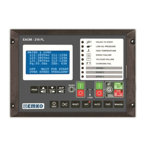
LOW OIL PRESSURE HIGH TEMPERATURE SPEED FAILURE VOLTAGE FAILURE V CHARGING FAIL START MAINS PROG STOP ENGINE RUNNING LOAD RESET AUTO TEST MANUAL TEST 204mm Figure 2.1 Front view. Figure 2.2 Panel cut-out EAOM-210 FLJ.eng / ver 0.0 Pages 7 / 132... -
Page 8: Electrical Connections
+BATTERY +BATTERY - BATTERY (Max. 10kHz) (Max. 10kHz) RS 232 LOAD LOAD COMMUNICATION BATTERY BATTERY VOLTAGE VOLTAGE 8-32 V 8-32 V 29 30 39 40 RS-232 Figure 2.4 Rear view. EAOM-210 FLJ.eng / ver 0.0 Pages 8 / 132... - Page 9 There is severe danger for human life in the case of unauthorized intervention. Keep the power off until all of the wiring is completed so that electric shock and trouble with the unit can be prevented. EAOM-210 FLJ.eng / ver 0.0 Pages 9 / 132...
-
Page 10: Figure 2.5 Eaom-210 Flj Three Phase Connections Schematic
Expansion I/O Module and / or J1939 ECUs CANL Figure 2.5 EAOM-210 FLJ three phase connections schematic. FUSE-1, FUSE-2, FUSE-3, FUSE-4, FUSE-5, FUSE-6, FUSE-7 1 A. T FUSE-8 should meet the current required by configurable output-2, 3, 4 – 15 A.T max FUSE-9 should meet the current required by solenoids (Max. - Page 11 3 The CAN interface requires that a 120 Ohms terminator is fitted to each end of the communications link. This termination resistor is fitted internally into the unit. So it is not required externally. EAOM-210 FLJ.eng / ver 0.0 Pages 11 / 132...
-
Page 12: Table 2.1 Unit Wiring
Horn or configurable relay output-1 16 A. Max. DC supply from Pin 32 +Battery supply input Supplies to Pin 36,37,38 Configurable relay output-2 5 A. Max. DC supply from Pin 35 EAOM-210 FLJ.eng / ver 0.0 Pages 12 / 132... - Page 13 5 A. Max. DC supply from Pin 35 Configurable relay output-4 5 A. Max. DC supply from Pin 35 - Battery supply to EAOM-210 FLJ Supplies to unit + Battery supply to EAOM-210 FLJ Supplies to unit CT Secondary for Earth current...
-
Page 14: Table 2.2 Unit Wiring Description
Gen. Contactor Open Relay Output. See Breakers Page Section for options available. Volts free contacts to 28. Gen. Contactor Open Relay Output. See Breakers Page Section for options available. Volts free contacts to 27. EAOM-210 FLJ.eng / ver 0.0 Pages 14 / 132... - Page 15 Configurable relay output-4. DC supply from Pin 35. See Configurable Output-4 Page Section for options available. - Battery input supplies EAOM-210 FLJ + Battery input supplies EAOM-210 FLJ CT Secondary for Earth current (IEA). CT Secondary for Earth current (IEA).
-
Page 16: Electronic Engines (Ecus) And Eaom-210Flj Unit
J1939 + Use only screened 120Ω impedance cable approved specifically for use in CanBus applications. CAN L 13 (Low) J1939 – Use only screened 120Ω impedance cable approved specifically for use in CanBus applications. EAOM-210 FLJ.eng / ver 0.0 Pages 16 / 132... - Page 17 J1939 + Use only screened 120Ω impedance cable approved specifically for use in CanBus applications. CAN L 32 (Low) J1939 – Use only screened 120Ω impedance cable approved specifically for use in CanBus applications. EAOM-210 FLJ.eng / ver 0.0 Pages 17 / 132...
-
Page 18: Section 3 Definition Of Front Panel And Programming
MANUAL TEST Number Comment: The red LED illuminates only when the EAOM-210 FLJ in the Programming Mode. The green LED indicates that Mains voltage and frequency is within limits and is ready to take over the load. The LED shows that the load is connected to the mains. It’s colour is green. - Page 19 128x64 Dot matrix LCD Display. This is used for displaying the electrical measurements during normal operation (features explained in section 5.1.1.), and editing/inspecting programming parameters in program mode. Failure Indicators. Detailed information available in section 5.1.2. EAOM-210 FLJ.eng / ver 0.0 Pages 19 / 132...
-
Page 20: Programming Procedure
Enter button without entering operator Operator or technician can access password. But user can not to the following page by pressing change the parameters. increment button EAOM-210 FLJ.eng / ver 0.0 Pages 20 / 132... - Page 21 Press prog button to exit By pressing ENTER button, decrement buttons to change the from Program Mode and user can access to all page. turn to operation screen. parameters in related page. EAOM-210 FLJ.eng / ver 0.0 Pages 21 / 132...
-
Page 22: Changing And Saving Operator Parameter Values
Parameter can be changed with increment and decrement buttons OPERATOR SECTION MAINS LEVELS PAGE MAINS UNDER VOLTAGE PROG Press Enter button to confirm the changed value and access to the following parameter. EAOM-210 FLJ.eng / ver 0.0 Pages 22 / 132... - Page 23 Operation Screen MAINS & LOAD L12: 380Vac I1: 126A L23: 380Vac I2: 126A L31: 380Vac I3: 126A Fq:50.0Hz 378A IEA: AUTO CRANKNG ATTEMP OVER SPEED PREALARM! PROG EAOM-210 FLJ.eng / ver 0.0 Pages 23 / 132...
-
Page 24: Accessing To The Technician Parameters
Enter button without entering technician Technician can access to the password. But user can not following page by pressing change the parameters. increment button EAOM-210 FLJ.eng / ver 0.0 Pages 24 / 132... - Page 25 ANALOGUE SENDER TECHNICIAN SECTION LINEARISATIONS Page ANALG.SENDR LIN.PAGE Technician can access to the following Technician can access to the former PROG page by pressing increment button. page by pressing decrement button. EAOM-210 FLJ.eng / ver 0.0 Pages 25 / 132...
- Page 26 DIGITAL CONFIGURABLE TECHNICIAN SECTION INPUT-4 Page DIG.CNF.INPUT-4 PAGE Technician can access to the following Technician can access to the former PROG page by pressing increment button. page by pressing decrement button. EAOM-210 FLJ.eng / ver 0.0 Pages 26 / 132...
- Page 27 CanBus Configuration page is disable, this page is ignored. Technician can access to the following Technician can access to the former PROG page by pressing increment button. page by pressing decrement button. EAOM-210 FLJ.eng / ver 0.0 Pages 27 / 132...
- Page 28 Operator can not access to this page. CONFIGURABLE OUTPUT-2 Page TECHNICIAN SECTION CONFIG.OUTPUT-2 PAGE Technician can access to the following Technician can access to the former PROG page by pressing increment button. page by pressing decrement button. EAOM-210 FLJ.eng / ver 0.0 Pages 28 / 132...
- Page 29 CanBus Configuration page is disable, this page is ignored. Technician can access to the following Technician can access to the former PROG page by pressing increment button. page by pressing decrement button. EAOM-210 FLJ.eng / ver 0.0 Pages 29 / 132...
- Page 30 Operator can not access to this page. LOAD/STOPPING TIMERS Page TECHNICIAN SECTION LOAD/STP.TIMERS PAGE Technician can access to the following Technician can access to the former PROG page by pressing increment button. page by pressing decrement button. EAOM-210 FLJ.eng / ver 0.0 Pages 30 / 132...
- Page 31 WORKING CALENDAR & EXERCISE TECHNICIAN SECTION Page WR.CALENDR&EXER.PAGE Technician can access to the following Technician can access to the former PROG page by pressing increment button. page by pressing decrement button. EAOM-210 FLJ.eng / ver 0.0 Pages 31 / 132...
- Page 32 Press prog button to exit By pressing ENTER button, decrement buttons to change the from Program Mode and user can access to all page. turn to operation screen. parameters in related page. EAOM-210 FLJ.eng / ver 0.0 Pages 32 / 132...
-
Page 33: Changing And Saving Technician Parameter Values
CT PRIMARY PROG Parameter can be changed with increment and decrement buttons TECHNICIAN SECTION GEN.CUR/POW.ACT.PAGE CT PRIMARY PROG Press Enter button to confirm the changed value and access to the following parameter. EAOM-210 FLJ.eng / ver 0.0 Pages 33 / 132... - Page 34 Operation Screen MAINS & LOAD L12: 380Vac I1: 126A L23: 380Vac I2: 126A L31: 380Vac I3: 126A Fq:50.0Hz 378A IEA: AUTO CRANKNG ATTEMP OVER SPEED PREALARM! PROG EAOM-210 FLJ.eng / ver 0.0 Pages 34 / 132...
-
Page 35: Programmable Function Definitions
GEN.OVER CURRENT Generator Over Current A AC 0 – 9999 9999 GEN.SHORT CIRCUIT Generator Short Circuit A AC 0 – 9999 9999 GEN.EARTH FAULT Generator Earth Fault A AC 0 – 9999 EAOM-210 FLJ.eng / ver 0.0 Pages 35 / 132... - Page 36 SENSING OPT. PICKUP EN/DIS & FLYWHEEL DISABLE: Speed sensing will not be derived from the magnetic pickup. 1-1000: Speed sensing will be derived from the magnetic pickup and the number is flywheel teeth on the engine. EAOM-210 FLJ.eng / ver 0.0 Pages 36 / 132...
- Page 37 LOOK MAINS FAILURE FOR MAINS CONTACTOR EN/DIS Disable: In the event of a mains failure the EAOM-210 FLJ will attempt to maintain the supply to the load for the incoming AC mains supply until the generator is available to go on load. In the event of a generator failure the module will default back to the incoming AC mains supply.
- Page 38 Example: Start/stop diagram for Diesel Engine. The formula signs and indices mean: Preheating time Engagement time Interval between 2 start attempts Engine delayed monitoring EAOM-210 FLJ.eng / ver 0.0 Pages 38 / 132...
- Page 39 EAOM-210 FLJ.eng / ver 0.0 Pages 39 / 132...
- Page 40 ‘ignition’ will be set. Example: Start/stop diagram for Gas Engine. The formula signs and indices mean: Interval between 2 start attempts Ignition delay Gas valve delay Engine delayed monitoring EAOM-210 FLJ.eng / ver 0.0 Pages 40 / 132...
- Page 41 EAOM-210 FLJ.eng / ver 0.0 Pages 41 / 132...
- Page 42 If the magnetic pickup is not detecting movement of the flywheel when this timer expires the engage attempt will terminate. Once all engage attempts have been made the module will generate ‘Fail to engage’ alarm. EAOM-210 FLJ.eng / ver 0.0 Pages 42 / 132...
- Page 43 Generator Over Speed Prealarm Return 500 – 5000 GEN.OVER SP.SHUTDWN Generator Over Speed Shutdown (dis) 500 – 5000 The parameters in this page are used for the generator speed low and high alarms. EAOM-210 FLJ.eng / ver 0.0 Pages 43 / 132...
- Page 44 3: analogue : The Oil pressure input is connected to a resistive type engine mounted temperature transducer. Note: If the Level Pre-alarm and Level Shutdown parameters are selected as disable, the Level showing is ignored. EAOM-210 FLJ.eng / ver 0.0 Pages 44 / 132...
- Page 45 Level 2 0 -300 LEVEL SENDER 3 Level Sender 3 0 -650 LEVEL 3 Level 3 0 -300 LEVEL SENDER 4 Level Sender 4 0 -650 LEVEL 4 Level 4 0 -300 EAOM-210 FLJ.eng / ver 0.0 Pages 45 / 132...
- Page 46 ECU if the selected ECU type is supporting the J1939 Remote control Messages. Available messages are engine start or stop. For some ECUs; Volvo Volvo Parameter Perkins Standard EMS2 EDC4 Remote Start Remote Stop EAOM-210 FLJ.eng / ver 0.0 Pages 46 / 132...
- Page 47 J1939 Red Stop Lamp Activation: 0- Active From Starting RED STOP ACTIVATION 0 – 2 1- Active From Safety On 2- Always Active RED STOP DELAY J1939 Red Stop Lamp Delay 0 - 250 EAOM-210 FLJ.eng / ver 0.0 Pages 47 / 132...
- Page 48 20 Transfer To Generator/Open Mains 21 Transfer To Mains/Open Generator 22 Remote Inhibit 23 Test on Load 24 Generator is supplying the load in OFF mode INPUT TIME DELAY Input active delay 0 - 250 EAOM-210 FLJ.eng / ver 0.0 Pages 48 / 132...
- Page 49 20 Transfer To Generator/Open Mains 21 Transfer To Mains/Open Generator 22 Remote Inhibit 23 Test on Load 24 Generator is supplying the load in OFF mode INPUT TIME DELAY Input active delay 0 - 250 EAOM-210 FLJ.eng / ver 0.0 Pages 49 / 132...
- Page 50 20 Transfer To Generator/Open Mains 21 Transfer To Mains/Open Generator 22 Remote Inhibit 23 Test on Load 24 Generator is supplying the load in OFF mode INPUT TIME DELAY Input active delay 0 - 250 EAOM-210 FLJ.eng / ver 0.0 Pages 50 / 132...
- Page 51 21 Transfer To Mains/Open Generator 22 Remote Inhibit 23 Test on Load 24 Generator is supplying the load in OFF mode 25 Low Oil Pressure INPUT TIME DELAY Input active delay 0 - 250 EAOM-210 FLJ.eng / ver 0.0 Pages 51 / 132...
- Page 52 21 Transfer To Mains/Open Generator 22 Remote Inhibit 23 Test on Load 24 Generator is supplying the load in OFF mode 25 High Temperature INPUT TIME DELAY Input active delay 0 - 250 EAOM-210 FLJ.eng / ver 0.0 Pages 52 / 132...
- Page 53 20 Transfer To Generator/Open Mains 21 Transfer To Mains/Open Generator 22 Remote Inhibit 23 Test on Load 24 Generator is supplying the load in OFF mode INPUT TIME DELAY Input active delay 0 - 250 EAOM-210 FLJ.eng / ver 0.0 Pages 53 / 132...
- Page 54 16 Auto Start Inhibit 17 Panel Lock 18 Scheduled Runs Inhibited 19 Reset Maintenance Alarm 20 Transfer To Generator/Open Mains 21 Transfer To Mains/Open Generator INPUT TIME DELAY Input active delay 0 - 250 EAOM-210 FLJ.eng / ver 0.0 Pages 54 / 132...
- Page 55 16 Auto Start Inhibit 17 Panel Lock 18 Scheduled Runs Inhibited 19 Reset Maintenance Alarm 20 Transfer To Generator/Open Mains 21 Transfer To Mains/Open Generator INPUT TIME DELAY Input active delay 0 - 250 EAOM-210 FLJ.eng / ver 0.0 Pages 55 / 132...
- Page 56 16 Auto Start Inhibit 17 Panel Lock 18 Scheduled Runs Inhibited 19 Reset Maintenance Alarm 20 Transfer To Generator/Open Mains 21 Transfer To Mains/Open Generator INPUT TIME DELAY Input active delay 0 - 250 EAOM-210 FLJ.eng / ver 0.0 Pages 56 / 132...
- Page 57 16 Auto Start Inhibit 17 Panel Lock 18 Scheduled Runs Inhibited 19 Reset Maintenance Alarm 20 Transfer To Generator/Open Mains 21 Transfer To Mains/Open Generator INPUT TIME DELAY Input active delay 0 - 250 EAOM-210 FLJ.eng / ver 0.0 Pages 57 / 132...
- Page 58 16 Auto Start Inhibit 17 Panel Lock 18 Scheduled Runs Inhibited 19 Reset Maintenance Alarm 20 Transfer To Generator/Open Mains 21 Transfer To Mains/Open Generator INPUT TIME DELAY Input active delay 0 - 250 EAOM-210 FLJ.eng / ver 0.0 Pages 58 / 132...
- Page 59 16 Auto Start Inhibit 17 Panel Lock 18 Scheduled Runs Inhibited 19 Reset Maintenance Alarm 20 Transfer To Generator/Open Mains 21 Transfer To Mains/Open Generator INPUT TIME DELAY Input active delay 0 - 250 EAOM-210 FLJ.eng / ver 0.0 Pages 59 / 132...
- Page 60 16 Auto Start Inhibit 17 Panel Lock 18 Scheduled Runs Inhibited 19 Reset Maintenance Alarm 20 Transfer To Generator/Open Mains 21 Transfer To Mains/Open Generator INPUT TIME DELAY Input active delay 0 - 250 EAOM-210 FLJ.eng / ver 0.0 Pages 60 / 132...
- Page 61 210 FLJ. If the devices providing this additional monitoring are connected to operate this input, the EAOM-210 FLJ will operate as if the incoming mains supply has fallen outside of limits, the generator will be instructed to start and take load. Removal of the input signal will cause the module to act if the mains has returned to within limits.
- Page 62 Stop push button. 11 GENERATOR CLOSED AUXILIARY This input is used to provide feedback to allow the EAOM-210 FLJ to give true indication of the contactor or circuit breaker switching status. It should be connected to the generator load switching device auxiliary contact.
- Page 63 / mains out of limits condition occurring. If this input is active and a remote start signal / mains failure occurs the EAOM-210 FLJ will not give a start command to the generator. If this input signal is then removed, the EAOM-210 FLJ will operate as if a remote start / mains failure has occurred, starting and loading the generator.
- Page 64 25 LOW OIL PRESSURE (FOR CONFIGURABLE INPUT-4) This input is used as the oil pressure failure input. 25 HIGH TEMPERATURE (FOR CONFIGURABLE INPUT-5) This input is used as the temperature failure input. EAOM-210 FLJ.eng / ver 0.0 Pages 64 / 132...
- Page 65 88 SYSTEM IN MANUAL MODE 89 SYSTEM IN OFF MODE 90 SYSTEM IN TEST MODE 91 UNDERSPEED SHUTDOWN 92 UNDERSPEED PRE-ALARM 93 ECU POWER 94 ECU STOP 95 WAITING FOR GENERATOR EAOM-210 FLJ.eng / ver 0.0 Pages 65 / 132...
- Page 66 88 SYSTEM IN MANUAL MODE 89 SYSTEM IN OFF MODE 90 SYSTEM IN TEST MODE 91 UNDERSPEED SHUTDOWN 92 UNDERSPEED PRE-ALARM 93 ECU POWER 94 ECU STOP 95 WAITING FOR GENERATOR EAOM-210 FLJ.eng / ver 0.0 Pages 66 / 132...
- Page 67 88 SYSTEM IN MANUAL MODE 89 SYSTEM IN OFF MODE 90 SYSTEM IN TEST MODE 91 UNDERSPEED SHUTDOWN 92 UNDERSPEED PRE-ALARM 93 ECU POWER 94 ECU STOP 95 WAITING FOR GENERATOR EAOM-210 FLJ.eng / ver 0.0 Pages 67 / 132...
- Page 68 88 SYSTEM IN MANUAL MODE 89 SYSTEM IN OFF MODE 90 SYSTEM IN TEST MODE 91 UNDERSPEED SHUTDOWN 92 UNDERSPEED PRE-ALARM 93 ECU POWER 94 ECU STOP 95 WAITING FOR GENERATOR EAOM-210 FLJ.eng / ver 0.0 Pages 68 / 132...
- Page 69 88 SYSTEM IN MANUAL MODE 89 SYSTEM IN OFF MODE 90 SYSTEM IN TEST MODE 91 UNDERSPEED SHUTDOWN 92 UNDERSPEED PRE-ALARM 93 ECU POWER 94 ECU STOP 95 WAITING FOR GENERATOR EAOM-210 FLJ.eng / ver 0.0 Pages 69 / 132...
- Page 70 88 SYSTEM IN MANUAL MODE 89 SYSTEM IN OFF MODE 90 SYSTEM IN TEST MODE 91 UNDERSPEED SHUTDOWN 92 UNDERSPEED PRE-ALARM 93 ECU POWER 94 ECU STOP 95 WAITING FOR GENERATOR EAOM-210 FLJ.eng / ver 0.0 Pages 70 / 132...
- Page 71 88 SYSTEM IN MANUAL MODE 89 SYSTEM IN OFF MODE 90 SYSTEM IN TEST MODE 91 UNDERSPEED SHUTDOWN 92 UNDERSPEED PRE-ALARM 93 ECU POWER 94 ECU STOP 95 WAITING FOR GENERATOR EAOM-210 FLJ.eng / ver 0.0 Pages 71 / 132...
- Page 72 88 SYSTEM IN MANUAL MODE 89 SYSTEM IN OFF MODE 90 SYSTEM IN TEST MODE 91 UNDERSPEED SHUTDOWN 92 UNDERSPEED PRE-ALARM 93 ECU POWER 94 ECU STOP 95 WAITING FOR GENERATOR EAOM-210 FLJ.eng / ver 0.0 Pages 72 / 132...
- Page 73 88 SYSTEM IN MANUAL MODE 89 SYSTEM IN OFF MODE 90 SYSTEM IN TEST MODE 91 UNDERSPEED SHUTDOWN 92 UNDERSPEED PRE-ALARM 93 ECU POWER 94 ECU STOP 95 WAITING FOR GENERATOR EAOM-210 FLJ.eng / ver 0.0 Pages 73 / 132...
- Page 74 88 SYSTEM IN MANUAL MODE 89 SYSTEM IN OFF MODE 90 SYSTEM IN TEST MODE 91 UNDERSPEED SHUTDOWN 92 UNDERSPEED PRE-ALARM 93 ECU POWER 94 ECU STOP 95 WAITING FOR GENERATOR EAOM-210 FLJ.eng / ver 0.0 Pages 74 / 132...
- Page 75 88 SYSTEM IN MANUAL MODE 89 SYSTEM IN OFF MODE 90 SYSTEM IN TEST MODE 91 UNDERSPEED SHUTDOWN 92 UNDERSPEED PRE-ALARM 93 ECU POWER 94 ECU STOP 95 WAITING FOR GENERATOR EAOM-210 FLJ.eng / ver 0.0 Pages 75 / 132...
- Page 76 88 SYSTEM IN MANUAL MODE 89 SYSTEM IN OFF MODE 90 SYSTEM IN TEST MODE 91 UNDERSPEED SHUTDOWN 92 UNDERSPEED PRE-ALARM 93 ECU POWER 94 ECU STOP 95 WAITING FOR GENERATOR EAOM-210 FLJ.eng / ver 0.0 Pages 76 / 132...
- Page 77 RESET button or by using an external ‘alarm reset’ input. 12 COMMON WARNING ALARM This output indicates that a warning alarm has been activated. This output is normally self- resetting on removal of the fault. EAOM-210 FLJ.eng / ver 0.0 Pages 77 / 132...
- Page 78 This output indicates that expansion configurable input 6 is active. 29 EXPNSION CONFIGURABLE INPUT7 ACTIVE This output indicates that expansion configurable input 7 is active. 30 EXPNSION CONFIGURABLE INPUT8 ACTIVE This output indicates that expansion configurable input 8 is active. EAOM-210 FLJ.eng / ver 0.0 Pages 78 / 132...
- Page 79 This output source has intended to be used to indicate a failure of the generator contactor or breaker. It can only be used if the module is configured to use ‘generator closed auxiliary’ feedback. EAOM-210 FLJ.eng / ver 0.0 Pages 79 / 132...
- Page 80 This output indicates that the generator is now due for maintenance either because it has used all the available running hours or the periodic maintenance time has expired. To clear the output a maintenance reset must be performed. EAOM-210 FLJ.eng / ver 0.0 Pages 80 / 132...
- Page 81 This output indicates that a low oil pressure shutdown has occurred. 72 OVER CURRENT ALARM This output indicates that the over current trip level has been reached. 73 OVERSPEED PRE-ALARM This output indicates that the over speed warning (pre-alarm) has occurred. EAOM-210 FLJ.eng / ver 0.0 Pages 81 / 132...
- Page 82 This output indicates that the stop pushbutton being operated. Once the button is released the output will become inactive. 87 SYSTEM IN AUTO MODE The output indicates that the module is in the Auto mode. EAOM-210 FLJ.eng / ver 0.0 Pages 82 / 132...
- Page 83 This timer dictates how long the module will wait after it has received a remote start signal before it will attempt to start. This prevent un-necessary starting on a fluctuating mains supply etc. EAOM-210 FLJ.eng / ver 0.0 Pages 83 / 132...
- Page 84 This timer is initiated once the engine is up and running. It delays loading the generator until it has stabilised. Once this timer is expired the ‘Close generator’ signal will be given and the generator is available to be loaded. EAOM-210 FLJ.eng / ver 0.0 Pages 84 / 132...
- Page 85 Parameters; GEN CLOSE BREAKER CONTACT TYPE, GEN CLOSE TIMER(if gen closed input selected), GEN OPEN TIMER(if gen closed input selected), MAIN CLOSE BREAKER CONTACT TYPE, MAINS CLOSE TIMER(if mains closed input selected), MAINS OPEN TIMER(if mains closed input selected), TRANSFER TIME. EAOM-210 FLJ.eng / ver 0.0 Pages 85 / 132...
- Page 86 Main Close Breaker Relay Type parameter is selected as 1), BREAKER OPEN PULSE TIME(if Gen Open Breaker Relay Type or Main Open Breaker Relay Type parameter is selected as 1), TRANSFER TIME. EAOM-210 FLJ.eng / ver 0.0 Pages 86 / 132...
- Page 87 Breaker close pulse time pulse time Gen. Closed Out. (NO) t[s] Gen. Closed Out. (NC) t[s] Gen. Open Out. (NO) t[s] Gen. Open Out. (NC) t[s] Opened Opened Gen. Shalter Closed Closed EAOM-210 FLJ.eng / ver 0.0 Pages 87 / 132...
- Page 88 This is used to monitor the opening of the generator contactor or breaker. It will only operate if an auxiliary input is configured as ‘Generator Closed Auxiliary’ and connected to the auxiliary on the generator contactor or breaker. Once a generator open signal is issued the EAOM-210 FLJ.eng / ver 0.0 Pages 88 / 132...
- Page 89 Auto Scroll Timer parameter. DIGITAL CONTRAST It is used to change contrast of LCD Display. BACKLIGHT ON/OFF 0- Backlight on. 1- Backlight off. EAOM-210 FLJ.eng / ver 0.0 Pages 89 / 132...
- Page 90 0 – 1 0 - Disabled 1 – With Ethernet CALL BACK SELECTION (dis)0 2 – With Modem 3 – With Ethernet and Modem SMS ENABLE SMS enable or disable ENAB/DIS EAOM-210 FLJ.eng / ver 0.0 Pages 90 / 132...
- Page 91 47- Short Circuit Electrical Trip 48- Earth Fault Electrical Trip 49- Can Bus error LED-2 FUNCTION Same as the LED-1 function 0 - 49 LED-3 FUNCTION Same as the LED-1 function 0 - 49 EAOM-210 FLJ.eng / ver 0.0 Pages 91 / 132...
- Page 92 12.20 o'clock (if it is enabled) WORK.PERIOD ON THU. (dis)0 The working function is Thursdays disabled. (1440) The working function is enabled whole day. (120) The working function is every Thursday enabled for 120 minutes. EAOM-210 FLJ.eng / ver 0.0 Pages 92 / 132...
- Page 93 Use this option to change the Technician password. It allows access to both operator and technician parameters section. BACK FACTORY DEFAULT If this parameter is selected as “Yes”, the unit’s parameters back to factory defaults. After this parameter is reset automatically to “No”. EAOM-210 FLJ.eng / ver 0.0 Pages 93 / 132...
-
Page 94: Pc Interface
There will be a short delay while the CD-ROM is accessed, then the disk contents will be displayed. Double click on “Install.exe”. EAOM-210 FLJ configuration software will be installed automatically on to your PC in its own folder(directory). It will also create “START MENU” items. EAOM-210 FLJ.eng / ver 0.0... -
Page 95: To Run Eaom-210 Flj Configuration Software
Then select Programs EAOM-210 FLJ PC SW(Folder) EAOM-210 FLJ V00.00 Then click on EAOM-210 FLJ configuration software. The below screen is shown. Click “Connect” in Comm. Settings menu. The “Connection and Device Location Settings” window is shown. EAOM-210 FLJ.eng / ver 0.0... - Page 96 Ethernet module / Dial-up or GSM modem. The RS-232 selection is made with the ‘Connect from Serial port’ check box. When the serial port selection is done, below screen is shown. EAOM-210 FLJ.eng / ver 0.0 Pages 96 / 132...
-
Page 97: Description
When the connection is established, main screen is shown; 3.6.4 Description The EAOM-210 FLJ unit communicates with PC by means of EAOM-210 FLJ PCIK. With EAOM-210 FLJ configuration software, the EAOM-210 FLJ unit’s parameters and status information can be reached over PC easily. Operator and Technician parameters can be viewed. -
Page 98: Window Menu
Language: This menu allows the user to choose language English or Turkish. Program Menu This menu allows load from EAOM-210 FLJ unit to PC or from PC to EAOM-210 FLJ unit the parameters which used for data communication and SMS. -
Page 99: Observation Menu
Generator volts (L1-N, L2-N, L3-N) Generator volts (L1-L2, L2-L3, L3-L1) Generator Hz Earth current (IEA) Load current total (IT) Next maintenance Working time Real time Run count Start count Battery Voltage Charge generator voltage EAOM-210 FLJ.eng / ver 0.0 Pages 99 / 132... - Page 100 In this window, you can also observe the output status, alarm status and change mode, start, stop, failure reset etc. For the monitoring the J1939 ECU messages, please click the “J1939” button and the below screen is shown. EAOM-210 FLJ.eng / ver 0.0 Pages 100 / 132...
- Page 101 Generator reactive power Q3 (kVAr) Generator total reactive power (kVAr) Generator reactive energy (kVArh) Generator apparent power S1 (kVA) Generator apparent power S2 (kVA) Generator apparent power S3 (kVA) Generator total apparent power (kVA) EAOM-210 FLJ.eng / ver 0.0 Pages 101 / 132...
- Page 102 Events: In this window the last 32 Event logs can be observed: EAOM-210 FLJ.eng / ver 0.0 Pages 102 / 132...
-
Page 103: Operator Parameters Menu
Operator can reach the parameters in this menu. Parameters are password protected. When the operator password is entered, it is compared with operator password that is registered on EAOM-210 FLJ unit. Entering To Operator Parameters Section Click “Mains Level” in Operator Parameter menu. Then Operator Password is monitored (if the operator password is zero, the password screen is ignored). -
Page 104: Technician Parameters Menu
(if the technician password is zero, the password screen is ignored). Enter the Technician Password and click OK button. If the password is correct, first page of the technician parameters (Mains Levels page) will be viewed. EAOM-210 FLJ.eng / ver 0.0 Pages 104 / 132... - Page 105 While the technician parameters window is showing, If user clicks “Upload All Parameters to the Controller” in Program menu, all of the technician parameters is loaded from PC to device. EAOM-210 FLJ.eng / ver 0.0 Pages 105 / 132...
-
Page 106: Adjustment Page (Calibration) Menu
Enter the Technician Password and click OK button. If the password is correct, the ADJUSMENT section will be viewed. Communication Settings Menu EAOM-210 FLJ.eng / ver 0.0 Pages 106 / 132... -
Page 107: Help Menu
Help: This menu allows the user to get information about mention to used the program and the menus in the program. About: Click “About” in Help menu. It gives information about the PC software version and MCU software version to the user. EAOM-210 FLJ.eng / ver 0.0 Pages 107 / 132... -
Page 108: Section 4 Commissioning
5. After a visual inspection to ensure it is safe to proceed, connect the battery supply. 6. On the EAOM-210 FLJ, press the Man (29) button. The associated LED (12) should light. 7. Press the Engine Start (21) button. At this moment the LED (7) lights on. -
Page 109: Auto Operation
1. Check that the mains is connected to the unit and is present. 2. Check the mains voltage readings on the display. 3. At the EAOM-210 FLJ, press the Auto (27) button. The LED (10) on the button should light. -
Page 110: Section 5 Operation
I3 - Load current L3 • IT – Vectorel total current • IEA - Earth current • AUTO - Working mode • CRANKNG ATTEMP - Engine cranking process is executing. (Engine status) • EAOM-210 FLJ.eng / ver 0.0 Pages 110 / 132... - Page 111 RED STOP LAMP! : Red Stop Lamp EARTH FAULT EL.TRIP! : Earth Fault Electrical Trip OVER CURRNT EL.TRIP! : Over Current Electrical Trip SHORT CIRCT EL.TRIP! : Short Circuit Electrical Trip CANBUS ERROR! : Can Bus Error. EAOM-210 FLJ.eng / ver 0.0 Pages 111 / 132...
- Page 112 L12 - Mains voltage L1-L2 • L23 - Mains voltage L2-L3 • L31 - Mains voltage L3-L1 • L-L AVERAGE – Phase to phase average • L-N AVERAGE – Phase to neutral average • EAOM-210 FLJ.eng / ver 0.0 Pages 112 / 132...
- Page 113 OVER SPEED PREALARM! S1 - Generator apparent power L1 • S2 - Generator apparent power L2 • S3 - Generator apparent power L3 • TOTAL - Generator total apparent power • EAOM-210 FLJ.eng / ver 0.0 Pages 113 / 132...
- Page 114 BATTERY VOL - Battery voltage • CHR.GEN.VOL - Charge generator voltage • OIL PRESS. - Engine Oil pressure (if enabled). • TEMPERATURE - Coolant temperature (if enabled). • LEVEL - Fuel Level (if enabled). • EAOM-210 FLJ.eng / ver 0.0 Pages 114 / 132...
- Page 115 FMI1: 0 OC1: SPN2: FMI2: 0 OC2: SPN3: FMI4: 0 OC3: AUTO CRANKNG ATTEMP OVER SPEED PREALARM! SPN1 – Suspect parameter number-1 (Active Faults DM1 with the Multipacket • Transport via J1939) EAOM-210 FLJ.eng / ver 0.0 Pages 115 / 132...
- Page 116 EXPAN.SPARE-2 ERROR: Expansion Spare-2 error EXPAN.SPARE-3 ERROR: Expansion Spare-3 error EXPAN.SPARE-4 ERROR: Expansion Spare-4 error EXPAN.SPARE-5 ERROR: Expansion Spare-5 error EXPAN.SPARE-6 ERROR: Expansion Spare-6 error EXPAN.SPARE-7 ERROR: Expansion Spare-7 error EXPAN.SPARE-8 ERROR: Expansion Spare-8 error EAOM-210 FLJ.eng / ver 0.0 Pages 116 / 132...
- Page 117 SPEED LOSS ERROR: Magnetic pickup loss of speed error TEMPER.HIGH PREALARM: High temperature pre-alarm TEMPER.HIGH SHUTDOWN: High temperature shutdown UNDER SPEED PREALARM: Generator low speed pre-alarm UNDER SPEED SHUTDOWN: Generator low speed shutdown EAOM-210 FLJ.eng / ver 0.0 Pages 117 / 132...
- Page 118 CRANKNG ATTEMP AUTO CRANKNG ATTEMP OVER SPEED PREALARM! OVER SPEED PREALARM! PROG PROG Press the previous button Press the next button to view the previous page. to view the next page. EAOM-210 FLJ.eng / ver 0.0 Pages 118 / 132...
- Page 119 CRANKNG ATTEMP AUTO CRANKNG ATTEMP OVER SPEED PREALARM! OVER SPEED PREALARM! PROG PROG Press the previous button Press the next button to view the previous page. to view the next page. EAOM-210 FLJ.eng / ver 0.0 Pages 119 / 132...
- Page 120 CRANKNG ATTEMP AUTO CRANKNG ATTEMP OVER SPEED PREALARM! OVER SPEED PREALARM! PROG PROG Press the previous button Press the next button to view the previous page. to view the next page. EAOM-210 FLJ.eng / ver 0.0 Pages 120 / 132...
- Page 121 CRANKNG ATTEMP AUTO CRANKNG ATTEMP OVER SPEED PREALARM! OVER SPEED PREALARM! PROG PROG Press the previous button Press the next button to view the previous page. to view the next page. EAOM-210 FLJ.eng / ver 0.0 Pages 121 / 132...
- Page 122 Press the next button to view Press the previous button to Press the page button to view the Mains & Load page. view the Miscellaneous page. the following Event Log page. EAOM-210 FLJ.eng / ver 0.0 Pages 122 / 132...
-
Page 123: Failure Indicators Description
This failure will not stop the generating set. 7- Configurable LED-1 (SPARE 1): The LED-1 can be configurable to simulate one of the conf. Inputs or error messages. EAOM-210 FLJ.eng / ver 0.0 Pages 123 / 132... -
Page 124: Mode Transition
When the mains is restored and stable, it will transfer the load back to the mains and, after a cool-down period, shut down the generator. EAOM-210 FLJ.eng / ver 0.0 Pages 124 / 132... -
Page 125: Test Operation
“AUTO” automatically. When the unit is in the “TEST MODE” if the Mains is gone, the unit will change run mode to “AUTO MODE” automatically. EAOM-210 FLJ.eng / ver 0.0 Pages 125 / 132... -
Page 126: Section 6 Fault Finding
1 alarm has occured. EXPAN. SPARE-2 ERROR! : This message indicates that an Expansion spare 2 alarm has occured. EXPAN. SPARE-3 ERROR! : This message indicates that an Expansion spare 3 alarm has occured. EAOM-210 FLJ.eng / ver 0.0 Pages 126 / 132... - Page 127 SHORT CIRCUIT ERROR! : This message indicates that a short circuit shutdown has occured. SHORT CIRCUIT WARNN! : This message indicates that a short circuit warning (pre- alarm) has occured. EAOM-210 FLJ.eng / ver 0.0 Pages 127 / 132...
-
Page 128: Table 6.1 Fault Finding
Engine failed to start EAOM-210 FLJ and restart the engine. after Pre-set number Check the signals that the EAOM-210 FLJ is using to determine if the of Attempts. engine has started. Refer to engine manual. Check wiring to starter solenoid. -
Page 129: Section 7 Block Diagram
LOAD L3 EARTH CURRENT SENSING ANALOG SENDERS LCD DISPLAY & FREQUENCY INDICATORS SENSING FROM GENERATOR VOLTAGE COUNTER & TIMER FREQUENCY SENSING MAGNETIC FROM PICK-UP MAGNETIC PICK-UP FAILURE & CONTROL INPUTS PUSH BUTTONS EAOM-210 FLJ.eng / ver 0.0 Pages 129 / 132... -
Page 130: Section 8 Specifications & Ratings
Accuracy: 0,25 % FS Generator Frequency From alternator voltage: 15.6 to 99.9 Hz (min. 35 VAC Ph-N) Accuracy: 0,25 % FS, Resolution: 0,1 Hz. CT secondary Charge Generator 220mA, max 4W. Excitation EAOM-210 FLJ.eng / ver 0.0 Pages 130 / 132... - Page 131 Event logs Working modes Engine status Error messages Program parameters Failure Indicators Failed to start Low oil pressure High temperature Speed failure Voltage failure Charging fail Spare 1 Spare 2 Spare 3 EAOM-210 FLJ.eng / ver 0.0 Pages 131 / 132...
- Page 132 Generator close relay output. 5A at DC supply voltage Configurable relay output-2. 5A at DC supply voltage Configurable relay output-3. 5A at DC supply voltage Configurable relay output-4. 5A at DC supply voltage EAOM-210 FLJ.eng / ver 0.0 Pages 132 / 132...
Need help?
Do you have a question about the EAOM-210 FLJ and is the answer not in the manual?
Questions and answers