Table of Contents
Advertisement
Quick Links
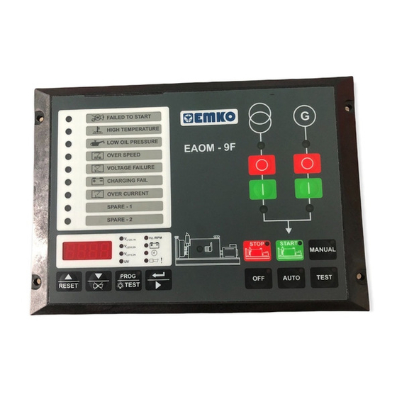
Automatic Transfer Switch Controllers,
-
Protection, control and metering
-
Automatic engine start/stop and load transfer
-
Automatic shutdown on fault condition
-
LED status and fault indication
-
Simple push-button controlled operation
-
Manual, automatic and test mode control
-
Two user-
configurable
-
One user-
configurable
-
Fully programmable
-
RS-232 communication port
-
Standard modem communication
- Monitors
3-phase mains supply voltage
Alternator voltage
Alternator frequency
Engine Speed
- Controls
Engine fuel supply or Engine Stopping
Starter motor
Alarm horn
Preheat
Automatic generator start
- Fail Monitoring
Mains Supply Voltage
Alternator Voltage and Frequency
Engine Speed
Engine Temperature
Oil Pressure
Charge Generator Voltage
- Programming using the buttons and display on the front panel or RS-232
communication port, using PC based software.
EAOM-9F
Flat Type
inputs
output
Instruction Manual. ENG
EAOM-9F
File
Programming
Settings
About
Observation
Operator Parameters
Technician Parameters
Adjustment
Measurement Values
Mains Voltage (L12)
0
Vac
Generator UV Voltage
Mains Voltage (L1N)
0
Vac
Generator Frequency
Mains Voltage (L23)
0
Vac
Battery Voltage
Mains Voltage (L2N)
0
Vac
Maintenance Time
Mains Voltage (L31)
0
Vac
Exercise Time
Mains Voltage (L3N)
0
Vac
Running Time
Failures
Start Failure
Over Speed
High Temperature
Generator Voltage Failure
Low oil Pressure
Charge Genarator Failure
Battery Fail
Emergency Stop
Routine Maintenance
Outputs
Mains Contactor Out
Configurable Out Output1
Generator Contactor Out
Selenoid Out
Modes
Off
Auto
Manual
Test
COM1
Communication
Battery voltage
Engine running time
Error Indication
Program Parameters
Load transfer on mains failure
Return to mains
Mains contactor
Generator contactor
Engine Start
Alternator Over Current
Emergency Stop
Maintenance Due
Low Battery Voltage
EAOM- F
0
Vac
0.0
Hz
11.0
Vdc
0 / 0
Hour / Day
0
Hour
0
Hour
Over Current
Spare-1
Spare-2
Start Out
Horn Out
Program
9 01 V01 04/21
Advertisement
Table of Contents

Related Manuals for EMKO EAOM-9F


Summary of Contents for EMKO EAOM-9F
- Page 1 EAOM-9F File Programming Settings About Observation Operator Parameters Technician Parameters Adjustment Measurement Values Mains Voltage (L12) Generator UV Voltage Mains Voltage (L1N) Generator Frequency Mains Voltage (L23) Battery Voltage 11.0 Mains Voltage (L2N) Maintenance Time 0 / 0 Hour / Day...
- Page 2 EU DECLARATION OF CONFORMITY Manufacturer’s Name : EMKO ELEKTRONIK A.S. Manufacturer’s Address : DOSAB, Karanfil Sk., No:6, 16369 Bursa, TURKEY The manufacturer hereby declares that the product: Product Name Electrical control equipment for generating sets Type Number : EAOM-9F Product Category...
-
Page 3: Table Of Contents
CONTENTS 1. Introduction ..............Page 4 1.1 General Specifications . -
Page 4: Introduction
Automatic mode. 1.2 Warranty EMKO Elektronik warrants that the equipment delivered is free from defects in material and workmanship. This warranty is provided for a period of two years. The warranty period starts from the delivery date. -
Page 5: Instaliation
2. Installation Ýçindekiler Before beginning installation of this product, please read the instruction manual and warnings below carefully. A visual inspection of this product for possible damage occured during shipment is recommended before installation. It is your responsibility to ensure that qualified mechanical and electrical technicians install this product. -
Page 6: Electrical Connection
3. Electrical Connection 3.1 1-Phase Connections Schematic MAINS CONTACTOR GENERATOR CONTACTOR MAINS LOAD GENERATOR MAINS VOLTAGE GENERATOR VOLTAGE 13 14 24 23 22 21 20 19 18 17 16 15 Magnetic Pickup (up to 10kHz) FUSE-2 D+(W.L) BATTERY NEGATIVE MUST BE GROUNDED 3.2 3-Phase Connections Schematic L3 L2 L1 N MAINS CONTACTOR... -
Page 7: Front Panel Description And Error Messages
The LED indicates that the load is connected to the mains. The LED shows that the load is supplied from the generator. The red LED illuminates only when EAOM-9F is in programming mode. This red LED shows that the unit is in the Manual mode. - Page 8 Number Comment The MAN button is used for changing operating mode of the unit to the Manual mode The OFF button is used for changing operating mode of the unit to the Off mode The TEST button is used for changing operating mode of the unit to the Test mode The AUTO button is used for changing operating mode of the unit to the Auto mode The Display Scroll Button is used for rotating between measurement screen in...
-
Page 9: Accessing To The Parameters
5. Accessing To The Parameters When button is Operation Screen Hz./RPM L12/L1N pressed, all leds and digits L23/L2N are energised, because L31/L3N prog button is also used as test button. Continue to PROG press the prog buton for 5 RESET TEST seconds, Operator Menu Entering screen is shown... - Page 10 Mains Voltage Hz./RPM L12/L1N Connection Level L23/L2N Parameter L31/L3N Press button for PROG accessing to the RESET TEST Value Mains Voltage Hz./RPM L12/L1N Connection Level L23/L2N Value L31/L3N Change the PROG parameter with RESET TEST buttons Mains Voltage Hz./RPM L12/L1N Connection Level L23/L2N Value...
-
Page 11: Parameters
6. Parameters The unit is extensively programmable through the front panel and via PC software. Definition of Parameter Default Unit Mains Voltage Connection Level Mains Voltage Disconnection Level Mains Voltage Upper Limit Alternator Voltage Lower Limit Alternator Voltage Upper Limit Speed Upper Limit 30.0 75.0... - Page 12 Definition of Parameter Default Unit Normal / Fail safe configuration of inputs Number 0 All normal 1 Temperature Fail-safe 2 Pressure Fail-safe 3 Temp. + Pressure Fail-safe 4 Conf. Input1 Fail-safe 5 Conf. Input1 + Temp. Fail-safe 6 Conf. Input1 + Pressure Fail-safe 7 Conf.
- Page 13 Unit Definition of Parameter Default Configurable Failure Input-1 Operation: Number 0 Force product into AUTO mode 1 Disable front panel controls 2 LED status indication only 3 LED flashes and alarm sounds while input is active 4 LED flashes and alarm sounds until reset 5 As “4”...
-
Page 14: Specifications
7. Specifications Equipment Use : Electrical control equipment for generating sets Housing& Mounting : 144 mm x 204 mm x 37 mm (including connectors) plastic housing for panel mounting Panel Cut-Out : 138 mm x 186 mm Protection : NEMA 4X (IP65 at front panel, IP20 at rear side). Weight : Approximately 0.45 Kg.
Need help?
Do you have a question about the EAOM-9F and is the answer not in the manual?
Questions and answers