Table of Contents
Advertisement
EPC-1, EPC-3 & EPC-4
EPC-1A, EPC-3A & EPC-4A
POULTRY CONTROLLER MANUAL
EMKO ELEKTRONIK A.S.
Demirtas Org. San. Bolg.
Karanfil Sk. No: 6 TR
16369 Bursa / TURKEY
Phone: +90 224 261 1900
Fax: +90 224 261 1912
Url: www.emkoelektronik.com.tr
e-mail: exposales@emkoelektronik.com.tr
Instruction Manual. ENG EPC_X 02 V03 07/13
Advertisement
Table of Contents

Related Manuals for EMKO EPC-1


Summary of Contents for EMKO EPC-1
- Page 1 EPC-1, EPC-3 & EPC-4 EPC-1A, EPC-3A & EPC-4A POULTRY CONTROLLER MANUAL EMKO ELEKTRONIK A.S. Demirtas Org. San. Bolg. Karanfil Sk. No: 6 TR 16369 Bursa / TURKEY Phone: +90 224 261 1900 Fax: +90 224 261 1912 Url: www.emkoelektronik.com.tr e-mail: exposales@emkoelektronik.com.tr...
- Page 2 ABOUT INSTRUCTION MANUAL Instruction manual of EPC consists of three main sections. Explanation of these sections are below. Also, there is another section which include technical specifications of the device. All titles and page numbers in instruction manual are in “CONTENTS” section. User can reach to any title with section number. Installation: In this section, physical dimensions of the device, panel mounting, electrical wiring, physical and electrical installation of the device to the system are explained.
- Page 3 CONTENTS Page 6 1. INTRODUCTION..........................Page 7 1.1 GENERAL SPECIFICATIONS..................... Page 8 1.2 WARRANTY..........................Page 8 1.3 MAINTENANCE.......................... 2. INSTALLATION........................... Page 8 2.1 GENERAL DESCRIPTION......................Page 9 2.2 DIEMENSIONS........................... Page 9 2.3 RIGHT SIDE VIEW........................Page10 Page11 2.4 PANEL CUT-OUT......................... Page11 2.5 ENVIRONMENTAL RATINGS.....................
-
Page 4: Table Of Contents
CONTENTS Page48 6.4 SCREENS PARAMETERS AND FUNCTIONS................Page48 6.4.1 TECHNICIAN PASSWORD....................Page49 6.4.2 HEATER1.......................... Page49 6.4.2.1 HEATING1 PARAMETERS................6.4.2.2 HEATER1 FUNCTION..................Page49 Page51 6.4.3 HEATER2.......................... Page51 6.4.3.1 HEATING2 PARAMETERS................Page51 6.4.3.2 HEATER2 FUNCTION..................Page53 6.4.4 COOLING.......................... Page53 6.4.4.1 COOLING PARAMETERS.................. 6.4.4.2 COOLING FUNCTION.................. - Page 5 EU DECLARATION OF CONFORMITY Manufacturer’s Name : EMKO ELEKTRONIK A.S. Manufacturer’s Address : DOSAB, Karanfil Sk., No:6, 16369 Bursa, TURKEY The manufacturer hereby declares that the product: Product Name : Poultry Controller Unit Type Number : EPC Product Category : Electrical equipment for measurement, control and...
- Page 6 1. INTRODUCTION FUNCTIONS EPC1 EPC3 EPC4 Pt-100 input -1, Room Temperature Measurement Pt-100 input -2, Room Temperature Measurement Pt-100 input -3, Outside Temperature Measurement 8 Relay Outputs for Fans 0-10 V Analog Output for Fans Heater-1 and Heater-2 Relay Outputs Cooling Relay Output Alarm Relay Output and 2 Alarm Signal Inputs Shutter Open/Close Relay outputs...
- Page 7 NOTE-1: If the device is EPC-1A, EPC-3A or EPC-4A, then this analog input is shutter feedback input. If the device is EPC-1 or EPC-3, there is no analog input. If the device is EPC-4, then this analog input is WEIGH-3 Analog input(0-10V).
- Page 8 1.2 WARRANTY EMKO Elektronik warrants that the equipment delivered is free from defects in material and workmanship. This warranty is provided for a period of two years. The warranty period starts from the delivery date. This warranty is in force if duty and responsibilities which are determined in warranty document and instruction manual performs by the customer completely.
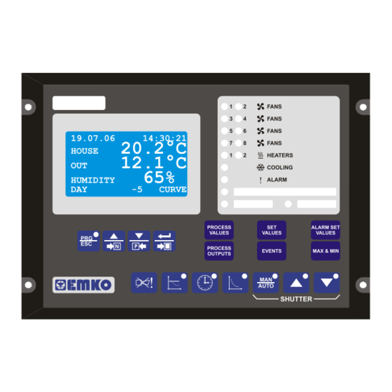
- Page 9 2.1 GENERAL DESCRIPTION Label Label Pocket Pocket Electrical Connection Mounting Holes Front Panel IP65 protection NEMA 4X Electrical Connection 2.2 DIMENSIONS 204mm FANS FANS FANS 19.07.06 14:30:21 FANS 20.2°C HOUSE HEATERS 12.1°C COOLING HUMIDITY ALARM CURVE PROCESS ALARM SET VALUES VALUES VALUES PROCESS...
- Page 10 2.3 RIGHT SIDE VIEW 16.5mm 34.5mm...
- Page 11 2.4 PANEL CUT-OUT R=4.5mm R=4.5mm 186 mm 196 mm 2.5 ENVIRONMENTAL RATINGS Operating Conditions Operating Temperature : -25°C to 70°C Max. Operating Humidity : 90% Rh (non-condensing) Altitude : Up to 2000m. Forbidden Conditions: Corrosive atmosphere Explosive atmosphere Home applications (The unit is only for industrial applications)
- Page 12 2.6 PANEL MOUNTING 1. Before mounting the device in your panel, make sure that the cut-out is of the right size 2. Make sure that the diameter of the holes are of the right size and coordinate of the holes are true. 3.
- Page 13 2.8 REMOVING FROM THE PANEL Before starting to remove the unit from panel, power off the unit and the related system. RESET 1. Loosen the screws. 2. Pull the unit through the front side of the panel...
- Page 14 3. INPUT AND OUTPUT CONNECTIONS 9 9 10 11 12 22 23 15 16 17 18 ROOM ROOM OUTSIDE TEMP 1 TEMP 2 TEMP PT-100 PT-100 PT-100 ANALOG OUTPUTS ANALOG INPUTS HUMIDITY DIGITAL INPUTS INPUT 1 INPUT 2 (0 - 10V (0 - 10V (0 - 10V (0-10 V...
- Page 15 3. INPUT AND OUTPUT CONNECTIONS 9 9 10 11 12 15 16 17 18 19 20 22 23 ROOM ROOM OUTSIDE TEMP 1 TEMP 2 TEMP PT-100 PT-100 PT-100 ANALOG OUTPUTS ANALOG INPUTS HUMIDITY INPUT 1 INPUT 2 SHUTTER DIGITAL INPUTS (0 - 10V FEEDBACK (0 - 10V...
- Page 16 Table 3.1 shows the connections and recommended cable sizes. Table 3.2 describes the functions of the connections. Table 3.1 Unit wiring Description Cable Size Notes (mm) Analog output’s common Analog output’s common Shutter analog output (EPC 3&4) Analog output Fan’s analog output Analog output Lighting analog output (EPC 3&4) Analog output...
- Page 17 4.RS-232 SERIAL INTERFACE, PROGRAMMING THE DEVICE OVER PC 4.1 CABLE CONNECTION BETWEEN RS-232 TERMINAL OF THE DEVICE AND PC 9 pin D connector 9 pin D connector female male White Brown Green Standard communication cable Note: For 9600 baud rate, cable length must be maximum 10 meters. 4.2 PC INTERFACE The PC interface kit comprises of a 9 pin D connector/FCC68(4 pin) connection lead with 2 meters of cable and the optional PC Software (Supplied on CD-ROM)
- Page 18 5. USER SECTION 5.1 EASY ACCESS DIAGRAM FOR PAGES PROCESS VALUES SYSTEM MONITORING (NOTE: 1) FEEDING CONSUMPTION NOTES: (EPC 3&4) 1: If CONTROL FUNC PAGE 2 PAGE FEEDING parameter is enabled then this page is visible (NOTE: 2) WEIGHING1 LOG (EPC 4) 2: If CONTROL FUNC PAGE 2 PAGE CHICKS W1 parameter is enabled then this page is visible...
- Page 19 5.2 SHORTCUT BUTTONS buttons are used to access to the pages, some pages can be accessed direct by pushing their buttons. These buttons are called “shortcut buttons”. Shortcut buttons and their pages are seen below; 19.07.06 14:30:21 20.2 ° HOUSE PROCESS 12.1 °...
- Page 20 Push button to access to curve pages or exit from curve mode pages and return to PROCESS VALUES page (NOTE:1) CURVE SETUP 19.07.07 14:30:21 CURVE STEP: 20.2°C HOUSE HOUSE TEMP: 0.0°C 12.1°C MIN. VENT : 0%00 MAX. VENT : 8%00 HUMIDITY HUMIDITY (NOTE: 3)
- Page 21 5.3 EDITING A PARAMETER To understand how to edit a parameter please read following example; INFLUENCE 2 T.O.TMP OFFS: T.RH OFFSET : NEG PRESSURE: 1. Sample display, INFLUENCE 2 T.O.TMP OFFS: T.RH OFFSET : 2. Push button. First parameter is selected, NEG PRESSURE: ENTER USER 3.
-
Page 22: Screens Parameters And Functions
5.4 SCREENS, PARAMETERS AND FUNCTIONS 5.4.1 PROCESS VALUE When the EPC is energized first PROCESS VALUES page is seen. PROCESS VALUES page has four different screens. All screens are seen below; 19.07.06 14:30:21 20.2°C HOUSE CONTROL FUNC PAGE 1 PAGE HUMIDITY parameter is enabled, 12.1°C CONTROL FUNC PAGE 1 PAGE OUTSIDE TEMP parameter is enabled. - Page 23 5.4.2 SYSTEM MONITORING SYSTEM MONITORING page has four different screens. All screens are seen below; SYSTEM MONITORING TMPSETCURVE: 20.0°C ROOM1 TEMP : 15.1°C CONTROL FUNC PAGE 1 PAGE CURVE parameter is enabled, ROOM2 TEMP : 19.4°C OUTSIDE TMP: 25.3°C CONTROL FUNC PAGE 1 PAGE OUTSIDE TEMP parameter is enabled. MAXVNTCURVE: 8%00 MINVNTCURVE:...
- Page 24 5.4.4 WEIGHING LOG (EPC 4) WEIGHING1 LOG WEIGHING2 LOG WEIGHING3 LOG 03.07.06 02:11:27 03.07.06 02:11:27 03.07.06 02:11:27 TARE TARE TARE LOG CLEAR LOG CLEAR LOG CLEAR ACT AVERAGE : 151GR ACT AVERAGE : 467GR ACT AVERAGE : 351GR YSTR AVERAGE: 143GR YSTR AVERAGE: 458GR...
- Page 25 5.4.5 ELECTRICITY ENERGY CONSUMPTION (EPC 4) ELECTRICITY ENERGY CONSUMPTION 03.07.06 02:11:27 RESET CONSUM: DAILY CONSUM: 15KWH TOTAL CONSUM: 5018KWH DAY NUMBER DATE: The unit shows current date (day.month.year). TIME: The unit shows current time (hour.minute.second). RESET CONSUM: Reset DAILY CONSUM and TOTAL CONSUM parameters (Range: NO- YES / Factory Setting: NO).
- Page 26 5.4.7 SET VALUES SET VALUES page showing depends on curve selection. If curve is enabled “Page II” is seen, otherwise “Page I” is seen. SET VALUES SET VALUES TEMP.HOUSE: 20.0°C TEMP.HEAT : -2.0°C TEMP.HEAT : -2.0°C TEMP.COOL : 2.0°C TEMP.COOL : 2.0°C HUMIDITY VENT.MIN...
- Page 27 Min. Vent CORRMINVENT (NOTE1) House [°C] House [°C] Settemp A(NOTE2) (NOTE1) (For EPC-1,EPC-3,EPC-4) SHUTTER PARAMETERS If VENTIL. PARAMETERS PAGE FAN CONT. parameter is BASIC&TUN. STROKE TIME: 100SEC STEP 1.0% then Shutter Analog value is 0V on basic ventilation section and Shutter motorized control operates only tunnel ventilation section.
- Page 28 5.4.9 FEEDING PARAMETERS (EPC 3&4) FEEDING PARAMETERS HR:MN FEED<KG> F1: 00:00 F2: 00:00 F3: 00:00 F4: 00:00 F5: 00:00 Start Time Feed Amount HR:MN (COLUMN): Step start time (Range: 00:00 - 23:59 / Factory Setting: 00:00). FEED <KG> (COLUMN): Feed amount for related step (Range: 0 KG - 10000 KG / Factory Settings please look below).
- Page 29 5.4.10 LIGHTING PARAMETERS (EPC 3&4) LIGHTING PARAMETERS HR:MN HR:MN OUT% L1: 00:00 00:00 L2: 00:00 00:00 L3: 00:00 00:00 L4: 00:00 00:00 L5: 00:00 00:00 Start Time Duration Analog Output HR:MN (START TIME COLUMN): Step start time (Range:00:00 - 23:59 / Factory Setting: 00:00). HR:MN (DURATION COLUMN): Step duration (Range:00:00 - 23:59 / Factory Setting: 00:00).
- Page 30 5.4.11.2 ALARM TYPES EPC has 10 different alarm types. These are listed below; ALARM SET VALUES 1- ABSOLUTE MIN alarm, ABSOLUTE MIN: 0.0°C 2- ABSOLUTE MAX alarm, ABSOLUTE MAX: 99.0°C 3- DIFFERENTIAL alarm, DIFFERENTIAL: 0.0°C TYPE :NONLATCH 4- ALARM1, 5- NEGATIVE PRESSURE alarm, 6- HUMIDITY SENSOR alarm, 7- NO ENOUGH FEED alarm, ALARM STATUS 1...
- Page 31 Third situation: If Temperature(NOTE1) is higher than ALARM SET VALUES ABSOLUTE MAX plus ALARM SET VALUES DIFFERENTIAL for more than a minute ALARM STATUS 1 DIFFERENTIAL alarm is switched ON. Outside temp. DIFFERENTIAL ALARM SET VALUES ALARM SET VALUES ALARM DIFFERENTIAL DIFFERENTIAL SET VENTILATION PAGE...
- Page 32 7. NO ENOUGH FEED alarm EPC always controls the silo just before to run a step. If FEED UNIT PARAMETERS UNIT parameter is WEIGHT and there is not enough feed in silo to run the step then ALARM STATUS 1 NO ENOUGH FEED alarm is switched ON.
- Page 33 5.4.12 PROCESS OUTPUTS PROCESS OUTPUTS HEATING1 HEATING2 COOLING HUMIDITY TUNNEL VENT. : 0%00 SHUTTER : 0%00 LIGHTING ANALOG: HEATING1: HEATER 1 output value (Range: 0% - 100%). HEATING2: HEATER 2 output value (Range: 0% - 100%). COOLING: COOLING output value (Range: 0% - 100%). HUMIDITY: HUMIDITY output value (Range: 0% - 100%).
- Page 34 5.4.14 ALARM STATUS ALARM STATUS 1 ALARM STATUS 2 ABSOLUTE MIN :OFF ROOM1 OFL :OFF ABSOLUTE MAX :OFF ROOM2 OFL :OFF DIFFERENTIAL :OFF OUTSIDE OFL :OFF ALARM1 :OFF NEGATIVE PRESSURE:OFF HUMIDITY SENSOR :OFF NO ENOUGH FEED :OFF ABSOLUTE MIN: Absolute min. alarm status (Range: OFF- ON). ABSOLUTE MAX: Absolute max.
- Page 35 5.4.16 INFLUENCES 5.4.16.1 INFLUENCE PARAMETERS INFLUENCE 1 INFLUENCE 2 F.L.O.T/MN.VNT: T.O.TMP OFFS: T.L.O.T/MN.VNT: -25.0 T.RH OFFSET : MAX.VENT.COOL : 8%00 NEG PRESSURE: F.L.O.T/T.OFF : NEG.PRE.TON : T.L.O.T/T.OFF : -25.0 NEG.PRE.TOFF: F.L.O.T/MN.VNT: Influence Factor Low Outside Temperature/ Minimum Ventilation set value (Range: NON, 0.5, 0.75, 1.0, 1.5, 2.0 / Factory Setting: NON).
- Page 36 5.4.16.2 INFLUENCE FUNCTIONS VENTILATION OUTPUT[%] 1. Influence cooling on maximum ventilation: If the COOLING PARAMETERS PAGE CONTROL Max. Vent (NOTE2) parameter is ON/OFF and COOLING OUTPUT is ON then Max. Vent value is equal to INFLUENCE 1 PAGE INFLUENCE 1 PAGE MAX. VENT. COOL MAX.
- Page 37 3. Influence factor low outside temperature on temperature offsets If outside temperature lower than inside to avoid draughts, ventilation stages are depended on INFLUENCE 1 PAGE F.L.O.T/T.OFF and INFLUENCE 1 PAGE T.L.O.T/T.OFF parameters. The influence starts 5 °C below the settemp. Temperature offset highest position [°C]...
- Page 38 5. Influence negative pressure input on ventilation and shutter: Negative pressure influence affects to reduce ventilation up to minimum ventilation. Also it set shutter to maximum value. As long as INFLUENCE 2 PAGE NEG PRESSURE parameter is different from NON, negative pressure is enabled.
- Page 39 5.4.18 CURVE 5.4.18.1 CURVE SETUP CURVE SETUP X is the number between CURVE STEP: 1 and 10 HOUSE TEMP: 0.0°C MIN. VENT : 0%00 MAX. VENT : 8%00 HUMIDITY DAY: Day set value (Range: 0- CURVE STEP2 DAY / Factory settings are below). HOUSE TEMP: House Temperature set value (Range: 0.0 °C- 50.0 °C / Factory settings are below).
- Page 40 5.4.18.2 CURVE FEEDING PARAMETERS (EPC 3&4) FEEDING PARAMETERS X is the number between CURVE STEP X 1 and 10 HR:MN FEED<KG> F1: 00:00 F2: 00:00 F3: 00:00 F4: 00:00 F5: 00:00 Start Time Feed Amount HR:MN COLUMN: Step start time (Range: 00:00 - 23:59 / Factory settings are below).
- Page 41 5.4.18.3 CURVE LIGHTING PARAMETERS (EPC 3&4) LIGHTING PARAMETERS X is the number between CURVE STEP X 1 and 10 HR:MN HR:MN OUT% L1: 00:00 00:00 L2: 00:00 00:00 L3: 00:00 00:00 L4: 00:00 00:00 L5: 00:00 00:00 Start Time Duration Analog Output HR:MN (START TIME COLUMN): Step start time (Range: 00:00 - 23:59 / Factory settings are below).
- Page 42 5.4.18.4 CURVE FUNCTION 1. What is a curve: CURVE SETUP Optimal temperature, ventilation, humidity, feeding and lighting values change CURVE STEP: day by day. EPC can automaticly adjust optimal values depend on entered HOUSE TEMP: 0.0°C parameters which are in CURVE SETUP PAGES. This function is called “curve”. MIN.
- Page 43 Humidity[%] (NOTE1) 12. day is between Step3 and Step4. So 12. day; humidity(NOTE1) is 73% Max.Vent (NOTE1) 5%00 4%00 3%00 12. day is between Step3 and Step4. So 12. day; Max.Vent(NOTE1) is 4%00 Min.Vent (NOTE1) 0%40 0%30 0%20 12. day is between Step3 and Step4. So 12. day; Min.Vent(NOTE1) is 0%30 NOTE1: If working with curve;...
- Page 44 Feeding Parameter (EPC 3&4) Page Step No Step10 Step9 Step8 Step7 Step6 Step5 Step4 Step3 Step2 Step1 At the graphic above, it is seen how feeding is working in curve mode. On 12. Day FEEDING PARAMETERS CURVE STEP 3 page is used for feeding (curve mode is enabled). The same page parameters are also used for 10, 11, 12, 13.
- Page 45 6. TECHNICIAN SECTION 6.1 FRONT PANEL 6.1.1 BUTTONS EXPLANATIONS 19.07.06 14:30:21 20.2°C HOUSE 12.1°C HUMIDITY FEEDING FEEDING LIGHTING LIGHTING HUMIDITY HUMIDITY BUTTONS: Used to access to technician parameters Process values page shortcut button field and escape function. Used to access to next page and increase Process output page shortcut button.
- Page 46 6.1.2 LEDS EXPLANATIONS 19.07.06 14:30:21 20.2°C HOUSE 12.1°C HUMIDITY FEEDING FEEDING LIGHTING LIGHTING HUMIDITY HUMIDITY Led no Explanation If technician field is accessed this led illuminates If influence pages are accessed this led illuminates If date setup page is accessed this led illuminates If curve pages are accessed this led illuminates If shutter mode is manual this led illuminates If shutter up relay is on this led illuminates...
- Page 47 6.2 EASY ACCESSING DIAGRAM FOR PAGES How to access to technician pages? There must be no selected parameter in current page. The current page must be one of the following pages which are in user field; PROCESS VALUES, SYSTEM MONITORING, FEEDING CONSUMPTION, WEIGHING1 LOG, WEIGHING2 LOG, WEIGHING3 LOG, ELECTRICITY ENERGY CONSUMPTION, WATER CONSUMPTION, SET VALUES, SET SHUTTER, FEEDING PARAMETERS, LIGHTING PARAMETERS, ALARM SET VALUES, PROCESS OUTPUTS, MAX MIN VALUES 1, MAX MIN VALUES 2, EVENTS...
-
Page 48: Technician Password
6.3 EDITING A PARAMETER AND CHANGING A PAGE SHUTTER PARAMETERS STROKE TIME: 100SEC STEP 0.1% 1. Sample display: SHUTTER PARAMETERS STROKE TIME: STEP 0.1% 2. Push button. The parameter is selected. SHUTTER PARAMETERS STROKE TIME: 3. Push buttons to edit parameter. STEP 0.1% Parameter has changed. -
Page 49: Heater1
6.4.2 HEATER1 6.4.2.1 HEATING1 PARAMETERS SENSOR: Sensor type set value HEATING1 PARAMETERS (Range: ROOM1, ROOM2, ROOM1&2 / Factory Setting: ROOM1). SENSOR ROOM1 CONTROL: Control mode set value CONTROL :PROPORTION (Range: NONE, ON/OFF, PROPORTION / Factory Setting: ON/OFF). SET POINT: RELATIVE HYST 1.0°C SET POINT: Set point type set value... - Page 50 2. PROPORTIONAL CONTROL MODE If the Temperature(NOTE1) is lower than settemp(NOTE2) minus HEATING1 PARAMETERS PAGE HYST control will be continuously on. If the Temperature(NOTE1) is higher than the settemp(NOTE2) then, control will be continuously off. If the measured temperature(NOTE1) is between settemp(NOTE2) and settemp(NOTE2) minus HEATING1 PARAMETERS PAGE HYST then, control output will be on for a portion of the HEATING1 PARAMETERS PAGE PERIOD.
-
Page 51: Heater2
6.4.3 HEATER2 6.4.3.1 HEATING2 PARAMETERS SENSOR: Sensor type set value HEATING2 PARAMETERS (Range: ROOM1, ROOM2, ROOM1&2 / Factory Setting: ROOM2). SENSOR ROOM1 CONTROL: Control mode set value CONTROL :PROPORTION (Range: NONE, ON/OFF, PROPORTION / Factory Setting: ON/OFF). SET POINT: RELATIVE HYST 1.0°C SET POINT: Set point type set value... - Page 52 2. PROPORTIONAL CONTROL MODE If the Temperature(NOTE1) is lower than settemp(NOTE2) minus HEATING2 PARAMETERS PAGE HYST control will be continuously on. If the Temperature(NOTE1) is higher than the settemp(NOTE2) then, control will be continuously off. If the measured temperature(NOTE1) is between settemp(NOTE2) and settemp(NOTE2) minus HEATING2 PARAMETERS PAGE HYST then, control output will be on for a portion of the HEATING2 PARAMETERS PAGE PERIOD.
-
Page 53: Cooling
6.4.4 COOLING 6.4.4.1 COOLING PARAMETERS SENSOR: Sensor type set value COOLING PARAMETERS (Range: ROOM1, ROOM2, ROOM1&2 / Factory Setting: ROOM1&2). SENSOR ROOM1 CONTROL: Control mode set value CONTROL :PROPORTION (Range: NONE, ON/OFF, PROPORTION / Factory Setting: ON/OFF). SET POINT: RELATIVE HYST 1.0°C SET POINT: Set point type set value... - Page 54 2. PROPORTIONAL CONTROL MODE If the Temperature(NOTE1) is higher than settemp(NOTE2) plus COOLING PARAMETERS PAGE HYST control will be continuously on. If the Temperature(NOTE1) is lower than the settemp(NOTE2) then, control will be continuously off. If the measured temperature(NOTE1) is between settemp(NOTE2) and settemp(NOTE2) plus COOLING PARAMETERS PAGE HYST then, control output will be on for a portion of the COOLING PARAMETERS PAGE PERIOD.
-
Page 55: Humidity
6.4.5 HUMIDITY 6.4.5.1 HUMIDITY PARAMETERS CONTROL: Control mode set value HUMIDITY PARAMETERS (Range: NONE, ON/OFF, PROPORTION CONTROL :PROPORTION / Factory Setting: PROPORTION) HYST HYST: Hysteresis set value PERIOD 40SEC OFFSET (Range: 0% - 99% / Factory Setting: 5%) PROP RAMP: 50SEC PERIOD: Period set value ALGORITHM:HUMIDIFICI... - Page 56 2. PROPORTIONAL CONTROL MODE If ALGORITHM parameter is selected as HUMIDIFI: If the humidity is lower than Set humidity(NOTE1) minus HUMIDITY PARAMETERS PAGE HYST control will be continuously on. If the humidity is higher than the Set humidity(NOTE1) then, control will be continuously off.
-
Page 57: Ventilation
6.4.6 VENTILATION 6.4.6.1 VENTILATION PARAMETERS VENTIL. PARAMETERS SHIFTING SHIFT&PRP PER: 10MIN FAN MIN TIME : 5SEC PRPRTN RAMP 50SEC SENSOR ROOM1 FAN CONT.: BASIC&TUN. FAN COUNT BAS:1 TOT:8 SHIFTING: Shift enabled or disabled or without chimney fans. (Range: OFF - CMN / Factory Setting: ON). SHIFT&PRP PER: Common set period value for proportion and shifting (Range: 1 MIN - 100 MIN / Factory Setting: 2 MIN). -
Page 58: Ventilation Function(Tunnel)
6.4.6.3 VENTILATION FUNCTION(TUNNEL) There are two different control outputs. 1. Fan linear ventilation control(TUNNEL VENT): There are eight fan stages to control fresh air level. It can be selected how much fans will work, by FAN COUNT : TOP parameter. Ventilation notation: x%y Process Output[%]... -
Page 59: Ventilation Function(Basic&Tun.)
6.4.6.4 VENTILATION FUNCTION(BASIC&TUNNEL) There are two different control outputs. 1. Fan ventilation control(BASIC&TUNNEL VENT): Basic ventilation fan count is selectable by BASIC FAN COUNT parameters. Remaining fans are tunnel fans. At this ventilation type, basic fans work only at minimum ventilation and tunnel fans work only at apart from minimum ventilation. - Page 60 6.4.6.4 VENTILATION FUNCTION(BASIC&TUNNEL) 2. Fan Analog ventilation control: Fan analog ventilation control Fans simultaneously works Analog with fan linear ventilation control. Output[V] (BASIC&TUNNEL VENT) 10.0 8.32 6.66 If SET VENTILATION PAGE FAN ANALOG 5.00 parameter is TUNNEL 3.32 1.66 House [°C] Fans Analog Output[V]...
-
Page 61: Technician Ventilation Parameters
6.4.6.5 TECHNICIAN VENTILATION PARAMETERS 1. Shifting fans (FAN CONT.:TUNNEL): VENTIL. PARAMETERS SHIFTING When VENTIL. PARAMETERS PAGE SHIFT&PRP PER parameter is SHIFT&PRP PER: 2MIN expired, working fan number is shifted right once. DLY BTWN FANS: 5SEC For example; 6. and 7. Fans are active and 8. Fan operates proportional PRPRTN RAMP 50SEC in Figure1... -
Page 62: Shutter Calibration
6.4.7 SHUTTER CALIBRATION(EPC1A,EPC3A,EPC4A) SHUTTER CALIBRATION SHUTTER CLOSE: SHUTTER OPEN: 1000 If SHUTTER PARAMETERS PAGE SHUT.FEEDB. parameter is ENABLE this page is shown. When calibrating shutter firstly push MAN/AUTO button to manually control the shutter. Press DOWN button to close the shutter. When the shutter fully closed select SHUTTER CLOSE parameter and change this parameter to YES. -
Page 63: Control Func Page
6.4.9 CONTROL FUNC PAGE 1 CONTROL FUNC PAGE 1 CONTROL FUNC PAGE 1 CURVE : DISABLE CURVE : DISABLE HUMIDITY ENABLE HUMIDITY ENABLE OUTSIDE TEMP: ENABLE OUTSIDE TEMP: ENABLE COMMUNICATE : ENABLE COMMUNICATE : ENABLE LOAD DEFAULT: LOAD DEFAULT: WATER CONSUM: ENABLE ELECT CONSUM: ENABLE... - Page 64 6.4.11 LIGHTING FUNCTION (EPC 3&4) 6.4.11.1 LIGHTING (ON/OFF MODE) FUNCTION If CONTROL FUNC PAGE 2 PAGE LIGHT CONT parameter is equal to ON/OFF then working princible is explained below; - First of all EPC has to capture START TIME to run a step. - Lighting relay output will be on between START TIME and START TIME plus DURATION TIME.
-
Page 65: Lighting(Modulate Mode) Function (Epc 3&4)
6.4.11.2 LIGHTING (MODULATE MODE) FUNCTION (EPC 3&4) If CONTROL FUNC PAGE 2 PAGE LIGHT CONT parameter is equal to MODULATE then working princible is explained below; CONTROL FUNC PAGE 2 - First of all EPC has to capture START TIME to run a step. FEEDING ENABLE - If OUT% is 0 then relay output is OFF otherwise relay output is ON... -
Page 66: Feeding (Epc 3&4)
6.4.12 FEEDING (EPC 3&4) 6.4.12.1 FEED UNIT PARAMETERS FEED UNIT PARAMETERS UNIT TIME FEED PER MIN: 6.0KG TARE REF WEIGHT 250KG TAKE REF WEIGHT: FEED OFFSET : UNIT: WEIGHT or TIME mode is used for feeding control depend on this parameter selection (Range: WEIGHT- TIME / Factory Setting: WEIGHT). -
Page 67: Feeding Weigh Adjustment (Epc 3&4)
6.4.12.2 FEEDING WEIGH ADJUSTMENT (EPC 3&4) 1. Feeding adjustment steps: FEED UNIT PARAMETERS page’s have three parameters are used to FEED UNIT PARAMETERS make feeding adjustment. 1. Take tare (TARE parameter), UNIT WEIGHT FEED PER MIN: 1.0KG 2. Enter reference weight (REF WEIGHT parameter), TARE 3. -
Page 68: Feeding System (Epc 3&4)
6.4.12.3 FEEDING SYSTEM (EPC 3&4) FEEDING PARAMETERS PAGES have two different screens. These screens depend on CONTROL FUNC PAGE 1 PAGE CURVE parameter. FEEDING PARAMETERS FEEDING PARAMETERS CURVE STEP X HR:MN FEED<KG> HR:MN FEED<KG> F1: 00:00 F1: 00:00 F2: 00:00 F2: 00:00 F3: 00:00 F3: 00:00... -
Page 69: Feeding Flow Charts (Epc 3&4)
6.4.12.4 FEEDING FLOW CHARTS (EPC 3&4) With Loadcell Without Loadcell START START CALCULATE IS THERE DURATION ENOUGH AND SET FEED TO TIMER USING CURRENT STEP STEP? DO NOT CHANGE IS FEEDING IS FEEDING THE STEP’S PAUSE THE DIGITAL DIGITAL FEED TIMER INPUT ON? INPUT ON? -
Page 70: Feeding (With Loadcell) Graphics (Epc 3&4)
6.4.12.5 FEEDING (WITH LOADCELL) GRAPHICS (EPC 3&4) If there is loadcell in the system then FEED UNIT PAREMETERS PAGE UNIT parameter must set to WEIGHT. For example; FEEDING PARAMETERS FEED UNIT PARAMETERS HR:MN FEED<KG> UNIT WEIGHT F1: 06:00 FEED PER MIN: 5.0KG F2: 10:00 TARE... -
Page 71: Feeding (Without Loadcell) Graphics (Epc 3&4)
6.4.12.6 FEEDING (WITHOUT LOADCELL) GRAPHICS (EPC 3&4) If there is no way to weigh feed then FEED UNIT PAREMETERS PAGE UNIT parameter must set to TIME. In this case EPC calculates the step working time by using FEED UNIT PAREMETERS PAGE FEED PER MIN parameter and current step’s “FEED <KG>... -
Page 72: Feeding Examples (Epc 3&4)
6.4.12.7 FEEDING EXAMPLES (EPC 3&4) Example 1; FEEDING PARAMETERS FEED UNIT PARAMETERS PAGE UNIT parameter: WEIGHT HR:MN FEED<KG> FEEDING CONSUMPTION PAGE TOTAL CONSUMPTION F1: 06:00 1500 parameter: 6500 kg F2: 10:00 6000 Consumption feed in last step: 1500 kg F3: 12:00 6000 After F1 step finished, new value of F4: 19:00... -
Page 73: Weight (Epc 4)
6.4.13 WEIGHT (EPC 4,EPC 4A) 6.4.13.1 WEIGHT1 ADJUSTMENT (EPC 4, EPC 4A) WEIGHT1 CALIBRATION TARE: REF WEIGHT: 5000GR TAKE REF WEIGHT: 5000GR LOAD TARE: Tare adjustment parameter (Range: NO- YES / Factory Setting: NO). REF WEIGHT: Reference weight value is used to make weight calibration (Range: 0 KG- 5000 KG / Factory Setting: 5000 KG). -
Page 74: Average Weigh1 (Epc 4)
6.4.13.4 AVERAGE WEIGH1 (EPC 4, EPC 4A) AVERAGE WEIGH1 INITIAL WEIGH: 100GR MINIMUM LIMIT: MAXIMUM LIMIT: INITIAL WEIGH: Curve start average weigh (Range: 0 GR- 5000 GR / Factory Setting: 100 GR). MINIMUM LIMIT: Minimum limit for recordable weigh (Range: 0 %- 50% / Factory Setting: 30%). MAXIMUM LIMIT: Maximum limit for recordable weigh (Range: 0 %- 50% / Factory Setting: 15%). -
Page 75: Weighing Parameters (Epc 4)
6.4.13.7 WEIGHING PARAMETERS (EPC 4, EPC 4A) WEIGHING PARAMETERS SS TIME 1.0SEC SS LIMIT VAL: 15GR AW MIN SMPL : AW SMPL PER : SS TIME: Steady state time for recordable weigh (Range: 0.3 SEC - 5.0 SEC / Factory Setting: 1.0 SEC). SS LIMIT VAL: Steady state limit value for recordable weigh (Range: 1 GR - 1000 GR / Factory Setting: 15 GR). -
Page 76: Weighing Adjustment (Epc 4)
6.4.13.8 WEIGHING ADJUSTMENT (EPC 4, EPC 4A) 1. Weighing adjustment steps: WEIGHT1 CALIBRATION To make weighing adjustment, WEIGHTX CALIBRATION pages are used. TARE: - WEIGHT1 CALIBRATION page is used to make WEIGHT1 0-10V input REF WEIGHT: 1000GR TAKE REF WEIGHT: adjustment. -
Page 77: Weighing (Epc 4)
6.4.13.9 WEIGHING (EPC 4, EPC 4A) 1. Weighing steps: WEIGHING PARAMETERS SS TIME 1.0SEC EPC can weigh the chickens via weigh channels and saves some data to give SS LIMIT VAL: 15GR information to user. AW MIN SMPL : User can monitor chickens status day by day via these data. AW SMPL PER : Flowing of the operation is quite simple and explained below;... -
Page 78: Water And Electricity Consumption (Epc 4)
6.4.14 WATER AND ELECTRICITY CONSUMPTION (EPC 4, EPC 4A) 6.4.14.1 WATER AND ELECTRICITY CONSUMPTION PER PULSE (EPC 4, EPC 4A) WATER AND ELECTRICITY CONSUMPTION PER PULSE ELECTRICITY: 1000WH/P WATER : 0.10LT/P ELECTRICITY: Electricity consumption per pulse (Range: 0 WH/Pulse - 9999 WH/Pulse / Factory Setting: 1000 WH/Pulse). WATER: Water consumption per pulse (Range: 0.00 LT/Pulse - 99.99 LT/Pulse / Factory Setting: 0.10 LT/Pulse). -
Page 79: Water Consumption (Epc 4)
6.4.14.3 WATER CONSUMPTION (EPC 4, EPC 4A) WATER AND ELECTRICITY WATER CONSUMPTION CONSUMPTION PER PULSE ELECTRICITY: 1000WH/P 03.07.06 02:11:27 WATER : 0.10LT/P RESET CONSUM: DAILY CONSUM: 1800LT TOTAL CONSUM: 14000LT DAY NUMBER EPC has a water consumption input which is called “WATER CONSUMP.” digital input. Consumption increases as many WATER AND ELECTRICITY CONSUMPTION PER PULSE PAGE WATER as each pulse Example:... -
Page 80: Nh3/Co2
6.4.15 NH3/CO2 6.4.15.1 NH3 CALIBRATION NH3 CALIBRATION MIN PPM : SAVE MIN: 0 PPM MAX PPM : 100 PPM SAVE MAX: 100PPM MIN PPM: Min ppm value that can be read by Nh3 sensor (Range: 0 - 100 / Factory Setting: 0). SAVE MIN: Parameter to save voltage for min PPM. -
Page 81: Sms Parameters
6.4.16 SMS PARAMETERS SMS PARAMETERS NUM1 : NNN NNN NN NN NUM2 : NNN NNN NN NN NUM3 : NNN NNN NN NN When CONNECTION parameter at MODBUS page is selected as ‘2’, modbus communication port is Rs485 and a GSM module can be connected on Rs232 port. At this stuation SMS feature is active. If an event defined at 5.4.15 EVENTS topic (page: 34) occurs, an SMS will be sent to defined GSM numbers. -
Page 82: Modbus
(Range: 0- 9999 / Factory Setting: 0). 6.4.19 ENTER CAL PASSWORD ENTER CAL PASSWORD 0000 PASSWORD PARAMETER: Factory Adjustment field password query IMPORTANT: UNAUTHORIZED ACCESSING TO ADJUSTMENT PAGES MAY EFFECT EPC’S WORKING EFFORT. EMKO HAS NO RESPONSIBILITY, IF CUSTOMER ACCESSES TO ANALOG ADJUSTMENT PAGES... -
Page 83: Specifications
6.4.18 COOLING SHUTTER PARAMETER (EPC 4B) COOLING SHUTTER STROKE TIM : 100SEC STEP 0.1% COOLING OFS: 0.0°C SHUTTER COR: 0.0% STROKE TIM: This is fully opening time of cooling shutter. The parameter’s range is 5-600 sec. To define this parameter correctly, firstly fully close the cooling shutter. Then, continuously open. Enter this parameter this opening time. - Page 84 Emko Elektronik Sanayi ve Ticaret A.Þ. Demirtaþ Organize Sanayi Bölgesi Karanfil Sk. No:6 16369 BURSA/TURKEY Phone : +90 224 261 1900 Fax : +90 224 261 1912 Thank you very much for your preference to use Emko Elektronik Products. Your Technology Partner www.emkoelektronik.com.tr...
Need help?
Do you have a question about the EPC-1 and is the answer not in the manual?
Questions and answers