Table of Contents
Advertisement
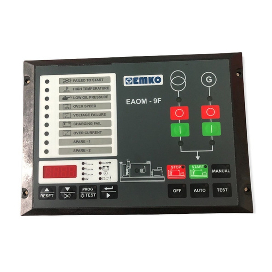
EAOM-9F & EAOM-9F ND
Automatic Transfer Switch Controllers,
-
Protection, control and metering
-
Automatic engine start/stop and load transfer
-
Automatic shutdown on fault condition
-
LED status and fault indication
-
Simple push-button controlled operation
-
Manual, automatic and test mode control
-
Two user-configurable inputs
-
One user-configurable output
-
Fully programmable
-
RS-232 communication port
-
Standard modem communication
- Monitors (Only EAOM-9F)
3-phase mains supply voltage
Alternator voltage
Alternator frequency
Engine Speed
- Controls
Engine fuel supply or Engine Stopping
Starter motor
Alarm horn
Preheat
Automatic generator start
- Fail Monitoring
Mains Supply Voltage
Alternator Voltage and Frequency
Engine Speed
Engine Temperature
Oil Pressure
Charge Generator Voltage
- Programming using the buttons and display on the front panel or RS-232
communication port, using PC based software.
EAOM-9F / 9F ND SOFT
File
Programming
Observation
Mains Voltage (L12)
Mains Voltage (L1N)
Mains Voltage (L23)
Mains Voltage (L2N)
Mains Voltage (L31)
Mains Voltage (L3N)
Start Failure
High Temperature
Low oil Pressure
Battery Fail
Mains Contactor Out
Generator Contactor Out
Off
COM1
Communication
Flat Type
Battery voltage
Engine running time
Error Indication
Program Parameters
Load transfer on mains failure
Return to mains
Mains contactor
Generator contactor
Engine Start
Alternator Over Current
Emergency Stop
Maintenance Due
Low Battery Voltage
Instruction Manual. ENG EAOM-9F & EAOM-9F ND 02 V00 07/07
Settings
About
Operator Parameters
Technician Parameters
Adjustment
Measurement Values
0
Vac
Generator UV Voltage
0
Vac
0
Vac
Generator Frequency
0.0
Hz
0
Vac
Battery Voltage
11.0
Vdc
0
Vac
Maintenance Time
0 / 0
Hour / Day
0
Vac
Exercise Time
0
Hour
0
Vac
Running Time
0
Hour
Failures
Over Speed
Over Current
Generator Voltage Failure
Spare-1
Charge Genarator Failure
Spare-2
Emergency Stop
Routine Maintenance
Outputs
Configurable Out Output1
Start Out
Selenoid Out
Horn Out
Modes
Auto
Manual
Test
Program
Advertisement
Table of Contents

Related Manuals for EMKO EAOM-9F


Summary of Contents for EMKO EAOM-9F
- Page 1 Engine Temperature Maintenance Due Oil Pressure Low Battery Voltage Charge Generator Voltage - Programming using the buttons and display on the front panel or RS-232 communication port, using PC based software. Instruction Manual. ENG EAOM-9F & EAOM-9F ND 02 V00 07/07...
- Page 2 ABOUT INSTRUCTION MANUAL Instruction manual of EAOM-9F & EAOM-9F consists of two main sections. Explanation of these sections are below. Also, there is another section which include technical specifications of the device. All titles and page numbers in instruction manual are in “CONTENTS”...
-
Page 3: Table Of Contents
4.3 PC INTERFACE 4.3.1 TECHNICAL SPECIFICATIONS 4.3.2 INSTALLATION INSTRUCTIONS 4.3.2.1 MINIMUM SYSTEM REQUIREMENTS 4.3.3 INSTALLING EAOM-9F / EAOM-9F SOFTWARE 4.3.4 USING OF EAOM-9F / EAOM-9F COMMUNICATION SOFTWARE 4.3.5 DESCRIPTION 4.3.6 OBSERVATION WINDOW 4.3.7 OPERATOR PARAMETERS WINDOW 4.3.8 TECHNICIAN PARAMETERS WINDOW 4.3.9 MAIN MENU... - Page 4 5.1.21 HORN BLINK SELECTION 5.1.22 ENGINE STARTING DELAY 5.1.23 ENGINE FUEL SELECTION AND FUEL-STARTER DELAY TIME 5.1.24 REMOTE CONTROL MODE SELECTION 5.2 CHANGING and SAVING OPERATOR PARAMETER VALUE 5.3 CHANGING and SAVING TECHNICIAN PARAMETER VALUE 6. COMMISSIONING..........................Page 6.1 MANUAL OPERATION 6.2 AUTO OPERATION 6.3 TEST MODE OPERATION 7.
- Page 5 Manufacturer Company Address: DOSAB, Karanfil Sokak, No:6, 16369 Bursa, Turkiye The manufacturer hereby declares that the product conforms to the following standards and conditions. Product Name Electrical control equipment for generating sets Model Number EAOM-9F & EAOM-9F ND Type Number : EAOM-9F & EAOM-9F Product Category...
-
Page 6: Preface
Engine running time Program Parameters EAOM-9F ND has no display, offers identical functionality and programming via RS-232, and can be used where electrical and engine metering is already in place. The unit is extensively programmable through the front panel, with password protection on two levels. -
Page 7: General Specifications
1.1 General Specifications +BATTERY POWER SUPPLY MICROCONTROLLER BATTERY TRANSISTOR VOLTAGE OUTPUTS SENSING ANALOG MAINS MAINS L1 & DIGITAL MAINS L2 GENERATOR CONVERTER MAINS L3 VOLTAGE SENSING GEN. L1 & CONDITIONING FREQUENCY SENSING FROM GENERATOR VOLTAGE COUNTER & RS-232+MODEM TIMER FREQUENCY COMM. -
Page 8: Warranty
1.2 Warranty EMKO Elektronik warrants that the equipment delivered is free from defects in material and workmanship. This warranty is provided for a period of two years. The warranty period starts from the delivery date. This warranty is in force if duty and responsibilities which are determined in warranty document and instruction manual performs by the customer completely. -
Page 9: Installation
Carefully unpack the unit and check for damage to the unit or to the cables supplied. Retain the packing in case of future need, e.g. returning the unit for calibration. Check the contents, as follows: • One EAOM-9F / EAOM-9F ND unit. • Operating Manual. • Screw fixings. -
Page 10: General Description
2.1 General Description Label Pocket Connection Terminals Mounting Holes Front Panel IP65 protection NEMA4X 96mm 2.2 Dimensions 204mm Figure 2.1. Front View Þekil 2.2. Side View... -
Page 11: Panel Cut-Out
2.3 Panel Cut-Out R=4.5mm R=4.5mm R=4.5mm R=4.5mm 186 mm 186 mm 196 mm 196 mm 2.4 Environmental Ratings Operating Conditions Operating Temperature : -25°C to 70°C Max. Operating Humidity : 90% Rh (non-condensing) Altitude : Up to 2000m. Forbidden Conditions: Corrosive atmosphere Explosive atmosphere Home applications (The unit is only for industrial applications) -
Page 12: Panel Mounting
2.5 Panel Mounting 1. Before mounting the device in your panel, make sure that the cut-out is of the right size 2. Make sure that the diameter of the holes are of the right size and coordinate of the holes are true. -
Page 13: Removing From The Panel
2.7 Removing from the Panel Before starting to remove the unit from panel, power off the unit and the related system. 1. Loosen the screws. 2. Pull the unit through the front side of the panel... -
Page 14: Electrical Wirings
3. ELECTRICAL WIRINGS 3.1 Terminal Layout and Connection Instructions OPEN COLLECTOR TRANSISTOR OUTPUTS MAX. 500 mA RS 232 COMMUNICATION INTERFACE Only qualified personnel and trained technicians should work on this equipment. This equipment contains internal circuits with voltage dangerous to human life. Do not open or dismantle the product enclosure. -
Page 15: Electrical Wiring Diagram
3.2 Electrical Wiring Diagram Single Phase Electrical Wiring MAINS CONTACTOR GENERATOR CONTACTOR MAINS LOAD GENERATOR MAINS VOLTAGE GENERATOR VOLTAGE 13 14 24 23 22 21 20 19 18 17 16 15 Magnetic Pickup (up to 10kHz) FUSE-2 D+(W.L) BATTERY NEGATIVE MUST BE GROUNDED Three Phase Electrical Wiring L3 L2 L1 N MAINS CONTACTOR... - Page 16 Table 2.1 shows the connections and recommended cable sizes. Table 2.2 describes the functions of the connections. Table 2.1 Unit wiring Description Cable Size (mm) Notes Mains PEN conductor Mains voltage input (L1) Mains voltage input (L2) 3 phase applications only Mains voltage input (L3) 3 phase applications only Alternator PEN conductor...
- Page 17 Table 2.2 Unit wiring description Pin Function Mains PEN conductor EAOM-9F / EAOM-9F ND Mains contactor transistor output. For mains contactor normally closed or normally open can be selected. (via external relay) Alternator contactor transistor output (via external relay) Configurable failure output. Can be programmed to provide transistor output closure when : alarm occurs, engine is running, unit is ready for automatic operation or preheat function.
-
Page 18: Rs-232 Serial Interface, Programming The Device Over Pc Or Modem
4.RS-232 SERIAL INTERFACE, PROGRAMMING THE DEVICE OVER PC OR MODEM 4.1 Cable Connection Between RS-232 Terminal of the Device and PC EAOM-9F 9 pin D connector 9 pin D connector female male White Brown Green Standard communication cable 4.2 Cable Connection Between RS-232 Terminal of the Device and Modem... -
Page 19: Pc Interface
EAOM-9F / EAOM-9F ND unit communicates with the PC using RS-232 communications. The PC software allows the EAOM-9F / EAOM-9F ND unit’s parameters and status information to be displayed on the PC screen. Operator and Technician parameters can be viewed. Parameters are password protected. -
Page 20: Observation Window
4.3.6 Observation Window When the program runs firstly, a window is shown to determine how the connection will be established: over modem or RS-232 communication port. This selection is made with the ‘Connect with Modem’ check box. If the comport settings are correct, when ‘Connect’ button is pressed, connection is established. - Page 21 When the connection is established, main screen is shown. Measurement Values Outputs Mains Voltage Mains Contactor Output Generator Voltage Generator Contactor Output Generator Frequency Configurable Output-1 Battery Voltage Solenoid output Maintenance Hour Start output Running Time Horn output Exercise Time Serial communication port (RS-232) Failures Modes...
-
Page 22: Operator Parameters Window
Download : With this menu user can load parameters from PC to EAOM-9F / EAOM-9F ND . Upload : User can load the parameters stored on EAOM-9F / EAOM-9F ND unit to PC. -
Page 23: Settings
4.3.9.3 Settings Communication Port Settings: With this menu, user can determine the serial port configurations of the PC Language: Turkish or English can be selected. Connect: With this menu, the window below is observed. According to the ‘Connect with Modem’ check status, connection can be establish over RS-232 port or modem. -
Page 24: Load The Configuration File From Disc
4.3.11 Accessing to the Technician Parameters Page Click Technician Parameter tab. Enter the technician password. If password is correct, all parameters will be viewed. 4.3.12 Accessing to the Adjustment Page Click Adjustment tab. Enter the technician password. If the password is correct, adjustment page will be shown. -
Page 25: Upload
4.3.15 Upload For loading parameters from EAOM-9F / EAOM-9F ND unit to PC follow the steps below. If user is in operator parameters window, only operator parameters will be viewed. If user is in Technician Parameters Window, all parameters will be viewed. Press 'Upload' in Program menu. While loading the parameters, the hour-glass cursor is displayed. -
Page 26: Parameters
5. PARAMETERS The unit is extensively programmable through the front panel and via PC software. Table 4 Programmable function definitions Definition of Parameter Default Unit Mains Voltage Connection Level Mains Voltage Disconnection Level Mains Voltage Upper Limit Alternator Voltage Lower Limit Alternator Voltage Upper Limit 30.0 75.0... - Page 27 Definition of Parameter Default Unit Normal / Fail safe configuration of inputs Number 0 All normal 1 Temperature Fail-safe 2 Pressure Fail-safe 3 Temp. + Pressure Fail-safe 4 Conf. Input1 Fail-safe 5 Conf. Input1 + Temp. Fail-safe 6 Conf. Input1 + Pressure Fail-safe 7 Conf.
- Page 28 Unit Definition of Parameter Default Configurable Failure Input-1 Operation: Number 0 Force product into AUTO mode 1 Disable front panel controls 2 LED status indication only 3 LED flashes and alarm sounds while input is active 4 LED flashes and alarm sounds until reset 5 As “4”...
-
Page 29: Program Functions
5.1 Program Functions 5.1.1 Mains Voltage P00 Mains Voltage Connection Level P01 Mains Voltage Disconnection Level P02 Mains Voltage Upper Limit P13 Mains Transition Delay In Automatic mode, the unit uses these parameters to decide when to switch the load between the mains supply and the alternator –... -
Page 30: Alternator Voltage
Number of Starting Attempts (P09) Starting Attempt Duration (P28) When the EAOM-9F / EAOM-9F ND receives an Engine Start command, it energises the start solenoid to drive the starter motor and energises the Fuel solenoid (if selected – see Section 5.1.9 Stop/Fuel selection) Starting attempt duration (P28) defines the maximum period for the start solenoid output is being active if one of the Engine Started Signals is not received (Refer to 5.1.7). -
Page 31: Engine Starting
This period begins when the EAOM-9F / EAOM- 9F ND has detected engine starting and has cut off the drive to the starter motor. This failure... -
Page 32: Control On Delay
(P32) defines a period during which any fault indications, except High Temperature, will be ignored by the EAOM-9F / EAOM-9F ND. Also, in the event of a mains failure, transfer of the load from mains to generator will be delayed until the end of the Control On Delay (P32) period. This period begins when the EAOM-9F / EAOM-9F ND has detected engine starting and has cut off the drive to the starter motor. -
Page 33: Configurable Output
P07 Periodic Maintenance Hour Set Value P08 Periodic Maintenance Hour Reset To ensure reliability, the generator must be serviced at regular intervals. The EAOM-9F / EAOM- 9F ND can be set to indicate when a service is due. Set Periodic Maintenance Day Set Value (P06) to the number of running hours between services. -
Page 34: Engine Exercise Function
5.1.19 Engine Exercise Function P15 Exercise Time P16 Exercise Duration Time Period This function allows the engine to be run automatically, without load, at fixed intervals, as specified by Exercise Time(P15). The engine runs for the number of minutes specified by Exercise Duration Time Period (P16). -
Page 35: Changing And Saving Operator Parameter Value
5.2 Changing and Saving Operator Parameter Value When button is Operation Screen Hz./RPM L12/L1N pressed, all leds and digits L23/L2N are energised, because L31/L3N prog button is also used as test button. Continue to PROG PROG press the prog buton for 5 RESET RESET TEST... - Page 36 Mains Voltage Hz./RPM L12/L1N Connection Level L23/L2N Parameter L31/L3N Press button for PROG PROG accessing to the RESET RESET TEST TEST Value Mains Voltage Hz./RPM L12/L1N Connection Level L23/L2N Value L31/L3N Change the PROG PROG parameter with RESET RESET TEST TEST buttons Mains Voltage...
-
Page 37: Changing And Saving Technician Parameter Value
5.3 Changing and Saving Technician Parameter Value When button is Operation Screen Hz./RPM L12/L1N pressed, all leds and digits L23/L2N are energised, because L31/L3N prog button is also used as test button. Continue to PROG PROG press the prog buton for 5 seconds, Operator Menu RESET RESET... - Page 38 Mains Voltage Hz./RPM L12/L1N Connection Level L23/L2N Parameter L31/L3N Press button for PROG PROG accessing to the RESET RESET TEST TEST Value Mains Voltage Hz./RPM L12/L1N Connection Level L23/L2N Value L31/L3N Change the PROG PROG parameter with RESET RESET TEST TEST buttons Mains Voltage...
-
Page 39: Commissioning
1. Check that the mains is connected to the unit and is present. 2. Check that the remote inhibit switch (if fitted) is set to disable (contact is open). 3. At the EAOM-9F / EAOM-9F ND, press the Auto (23) button. The LED (14) on the button should light. -
Page 40: Test Mode Operation
6.3 Test Mode Operation 1. Check that the mains is connected to the unit. 2. Press the Test (22) button. The LED (13) should light. 3. Check that the generator starts and that the load is still connected to the mains. 4. -
Page 41: Operation
The LED indicates that the load is connected to the mains. The LED shows that the load is supplied from the generator. The red LED illuminates only when EAOM-9F / -9F ND is in programming mode. This red LED shows that the unit is in the Manual mode. -
Page 42: Display Mode Indicators
Number Comment The MAN button is used for changing operating mode of the unit to the Manual mode The OFF button is used for changing operating mode of the unit to the Off mode The TEST button is used for changing operating mode of the unit to the Test mode The AUTO button is used for changing operating mode of the unit to the Auto mode The Display Scroll Button is used for rotating between measurement screen in... -
Page 43: Mode Transition
8.3 Mode Transition The mode can be changed at any time. A change in mode will not effect the current state of the generator or load connection. For example; if the unit is in Auto mode with the generator running and the load running on the generator, changing the mode to Manual will not effect the operating state. -
Page 44: Fault Finding
To obtain this indication, the engine must have been running for at least the period specified by the Oil Pressure By-Pass Time (P31). If this fault occurs, the EAOM-9F will stop the engine without any Engine Cooling Period (P10). -
Page 45: Over Current Led
Failure Reset (16) to remove the indication and restore EAOM-9F operation. This failure is indicated with Led in EAOM-9F ND and as error messages in EAOM-9F. When this failure occurs in EAOM-9F the led with exclamation mark starts to flash and user can see the error messages with the Scroll button 9.1.10... - Page 46 Check solenoid transistor output activated, (Fuel Solenoid if selected) after Pre-set Number Of Attempts. Check the signals that the EAOM-9F is using to determine if the engine has started. Refer to the engine manual. Check wiring to starter solenoid. Starter motor Check battery supply.
-
Page 47: Programmable Parameters
10. PROGRAMMABLE PARAMETERS Definition of Parameter Unit User Def.Value Mains Voltage Connection Level Mains Voltage Disconnection Level Mains Voltage Upper Limit Alternator Voltage Lower Limit Alternator Voltage Upper Limit Speed Upper Limit 30.0 75.0 Periodic Maintenance Day Set Value 0000 9999 Hour Periodic Maintenance Hour Set Value Press ‘Silence Alarm’... - Page 48 Definition of Parameter Unit User Def.Value Configurable input-1 operation Number Configurable input-2 operation Number Configurable input-1 delay time Second Configurable input-2 delay time Second Configurable Output Number 0=Mains contactor Number is NO P43 Mains Contactor Selection 1=Mains contactor is NC 0=Gas P44 Motor Fuel (Gas/Diesel) Selection 1=Diesel...
-
Page 49: Specifications
1, Configurable input 2, Low battery voltage (observed with led in EAOM-9F ND, failure message in EAOM-9F), Maintenance due (observed with led in EAOM-9F ND, failure message in EAOM-9F) Emergency stop (observed with led in EAOM-9F ND, failure message...
Need help?
Do you have a question about the EAOM-9F and is the answer not in the manual?
Questions and answers