Table of Contents
Advertisement
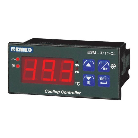
ESM-3711-CL 77 x 35 DIN Size,
Minimum & Maximum Temperature Record,
Digital, ON / OFF Cooling Controller
- 3 Digits display
- NTC input or,
PTC input or,
2 Wire PT-100 input or,
2 Wire PT-1000 input (It must be determined in order.)
- ON / OFF Control
- Adjustable process offset value
- Set value boundaries
- Relay or SSR driver output
- Digital Input (Door switch input)
- Open door alarm
- Logging starting option parameter
- Operation selection of compressor operate continuously, stops
or operates periodically in case of probe defect
- Compressor protection delays
- Defrost (Off-Cycle) function
- Adjustable defrost time from front panel
- Manual defrost from front panel
- Defrost parameters
- Alarm parameters
- Adjustable internal buzzer according to the defrost, prob defect
And alarm status
- Button protection
- Password protection for programming mode
Instruction Manual. ENG ESM-3711-CL 02 V01 07/13
Advertisement
Table of Contents

Related Manuals for EMKO ESM-3711-CL


Summary of Contents for EMKO ESM-3711-CL
- Page 1 - Manual defrost from front panel - Defrost parameters - Alarm parameters - Adjustable internal buzzer according to the defrost, prob defect And alarm status - Button protection - Password protection for programming mode Instruction Manual. ENG ESM-3711-CL 02 V01 07/13...
- Page 2 ABOUT INSTRUCTION MANUAL Instruction manual of ESM-3711-CL Cooling Controller consists of two main sections. Explanation of these sections are below. Also, there are other sections which include order information and technical specifications of the device. All titles and page numbers in instruction manual are in “CONTENTS”...
-
Page 3: Table Of Contents
1.2 ORDERING INFORMATION 1.3 WARRANTY 1.4 MAINTENANCE 2.INSTALLATION............................ Page 2.1 GENERAL DESCRIPTION 2.2 FRONT VIEW AND DIMENSIONS OF ESM-3711-CL COOLING CONTROLLER 2.3 PANEL CUT-OUT 2.4 ENVIRONMENTAL RATINGS 2.5 PANEL MOUNTING 2.6 INSTALLATION FIXING CLAMP 2.7 REMOVING FROM THE PANEL 3.ELECTRIAL WIRINGS......................... - Page 4 EU DECLARATION OF CONFORMITY Manufacturer Company Name : Emko Elektronik A.S. Manufacturer Company Address: DOSAB, Karanfil Sokak, No:6, 16369 Bursa, Turkiye The manufacturer hereby declares that the product conforms to the following standards and conditions. Product Name : Cooling Controller...
-
Page 5: General Specifications
1.Preface ESM-3711-CL series cooling controllers are designed for controlling cooling process. They can be used in many applications with their easy-use, On / Off control form, min & max temperature recording and defrost properties. Some application and application fields which they... -
Page 6: Ordering Information
Customer 1.3 Warranty EMKO Elektronik warrants that the equipment delivered is free from defects in material and workmanship. This warranty is provided for a period of two years. The warranty period starts from the delivery date. This warranty is in force if duty and responsibilities which are determined in warranty document and instruction manual performs by the customer completely. -
Page 7: Installation
2.Installation Before beginning installation of this product, please read the instruction manual and warnings below carefully. In package , - One piece unit - Two pieces mounting clamps - One piece instruction manual A visual inspection of this product for possible damage occured during shipment is recommended before installation. -
Page 8: General Description
2.1 General Description Mounting Clamp Front Panel IP65 protection NEMA 4X Panel surface (maximum thickness 15 mm / 0.59 inch) 2.2 Front View and Dimensions of ESM-3711-CL Cooling Controller ESM - 3711-CL °C Cooling Controller 77 mm / 3.03 inch... -
Page 9: Panel Cut-Out
Maximum 15 mm / 0.59 inch 58.5 mm / 2.30 inch 4 mm / 0.16 inch 2.3 Panel Cut-Out 110 mm / 4.33 inch (min) 71 mm / 2.79 inch... -
Page 10: Environmental Ratings
2.4 Environmental Ratings Operating Conditions Operating Temperature : 0 to 50 °C Max. Operating Humidity : 90% Rh (non-condensing) Altitude : Up to 2000 m. Forbidden Conditions: Corrosive atmosphere Explosive atmosphere Home applications (The unit is only for industrial applications) 2.5 Panel Mounting 1-Before mounting the device in your panel, make sure that the cut-out is of... -
Page 11: Installation Fixing Clamp
2.6 Installation Fixing Clamp The unit is designed for panel mounting. 1-Insert the unit in the panel cut-out from the front side. 2- Insert the mounting clamps to the fixing sockets that located left and right sides of device and make the unit completely immobile within the panel Montage of the unit to a system must be done with it’s own fixing clamps. -
Page 12: Electrial Wirings
3.Electrical Wiring You must ensure that the device is correctly configured for your application. Incorrect configuration could result in damage to the process being controlled, and/or personal injury. It is your responsibility, as the installer, to ensure that the configuration is correct. Device parameters has factory default values. -
Page 13: Electrical Wiring Diagram
3.2 Electrical Wiring Diagram Electrical wiring of the device must be the same as ‘Electrical Wiring Diagram’ below to prevent damage to the process being controlled and personnel injury. CAT II P/N : ESM-3711-CL OUTPUT DIGITAL NTC, INPUT PTC, PT-100,... -
Page 14: View Of The Device Label
3.3 View of the Device Label Device Label for PT-100 Type ( -19.9 ; 99.9 ) scaled, 230V Supply Voltage Input and Relay Output CAT II P/N : ESM-3711-CL - 5.09.0.1/00.00/1.0.0.0 PT-100 OUTPUT DIGITAL 230 V ± 15% (-19.9 to 99.9 °C... -
Page 15: Supply Voltage Input Connection Of The Device
3.4 Supply Voltage Input Connection of the Device Connection of Supply Voltage Connection of Supply Voltage Input Input Note-1 Note-1 External External Fuse Fuse (1 A T) (1 A T) Power Power Supply Supply Switch Switch Supply Voltage Supply Voltage 230 V (±... -
Page 16: Temperature Sensor Input Connection
3.5 Temperature Sensor Input Connection 3.5.1 PTC Connection WHITE Input resistance is greater than 10 M Pay attention the cable colours of PTC probe while doing the PTC probe connection. 3.5.2 NTC Connection Input resistance is greater than 10 M 3.5.3 PT-100 and PT-1000 Connections PT-100 PT-1000... -
Page 17: Galvanic Isolation Test Values Of Esm-3711-Cl Cooling Controller
3.6Galvanic Isolation Test Values of ESM-3711-CL Cooling Controller 2000 V ( ESM-3711-CL.5..) 500 V ( ESM-3711-CL.3..) Supply Voltage Ground Input 2000 V 2000 V Output-1 Relay Output 2000 V Optional SSR Driver Output 2000 V Analogue Input 2000 V... -
Page 18: Output Connections
3.7 Output Connections 3.7.1 Relay Output Connection Device 10 A T Fuse Load Fuses must be selected according to the application. 3.7.2 SSR Driver Output Connection Device Last Control Element (SSR) Max. 15 V Max. 15mA Fuse Load Fuses must be selected according to the application. -
Page 19: Front Panel Definition And Accessing To The Menus
4. Front Panel Definition and Accessing to the Menus Led Indication of set value Led Indication of programming changing mode is active mode is active Compressor output led Note-1 (If it blinks, Increment button, In compressor protection main operation time is active) screen It is used to ESM - 3711-CL show maximum... -
Page 20: Changing And Saving Temperature Set Value
4.2 Changing and Saving Temperature Set Value Temperature Set Value Screen Main Operation Screen °C °C When SET button is pressed, SV led Change the temperature lights on and temperature set value is set value with increment shown on the display and decrement buttons Temperature Set Value Screen Main Operation Screen... -
Page 21: Programming Mode Parameters List
4.4 Programming Mode Parameters List Hysteresis Parameter for Compressor Output ( Default = 3 ) From 1 to 100°C for PT-100 (-50°C , 400°C) and PT-1000 (-50°C , 400°C), From 0.1 to 10.0°C for PT-100 (-19.9°C, 99.9°C) and PT-1000 (-19.9°C, 99.9°C), From 1 to 20°C for PTC (-50°C, 150°C) and NTC (-50°C, 100°C), From 0.1 to 10.0°C for PTC (-19.9°C, 99.9°C) and NTC (-19.9°C, 99.9°C) Temperature... - Page 22 Compressor Start Delay at Power On Parameter ( Default = 0 ) When power is first applied to the device,This time delay must be expired for activation of compressor. It can be adjusted from 0 to 20 minutes. Compressor Stop-Start Delay Parameter ( Default = 0 ) When compressor is inactive, this time delay must be expired for activation of the compressor.
- Page 23 Buzzer Function Selection Parameter( Default = 1 ) Buzzer is inactive. Buzzer is active during defrost operation. Buzzer is active if an alarm occurs. Buzzer is active during sensor failures. Buzzer is active during defrost operation, alarm or sensor failures. Buzzer Activity Time ( Default = It can be adjusted from 1 to 99 minutes.
-
Page 24: Defrost On/Off Operation
4.5 Defrost ON/OFF Operation Compressor output led 3 secs When defrost time parameter value 1, button protection parameter value = 0 or 2 and cooling operation is performed (compressor output led is on), if defrost button is pressed for 3 seconds in main operation screen, defrost operation starts and defrost active becomes active. -
Page 25: Operation Graphics Of Esm-3711-Cl Cooling Controller
4.7 Operation Graphics of ESM-3711-CL Cooling Controller 1-If Defrost Time Parameter Defrosting Repeat Cycle Defrost at Power On Parameter = 1 and Defrost Delay at Power On Parameter Power Time Time Defrost time starts with button. Defrost Time °C Time... -
Page 26: Easy Access Diagram Of Programming Mode Parameters
4.8 Easy Access Diagram of Programming Mode Parameters 5 secs. °C °C °C Password Entering Main Operation Screen Programming Mode Entering Screen Screen Enter password with increment and decrement buttons °C °C °C Minimum Set Value Password Entering Press SET/OK button for Hysteresis accessing parameters Screen... - Page 27 4.8 Easy Access Diagram of Programming Mode Parameters °C °C °C Alarm Maximum Alarm Minimum Alarm Delay °C °C °C Buzzer is active Alarm Delay After Buzzer Function Power On Selection during this time °C °C °C Button Protection Logging Option Logging Starting Time After Parameter Door Switch is Closed...
-
Page 28: Entering To The Programming Mode, Changing And Saving Parameters
4.9 Entering to the Programming Mode, Changing and Saving Parameters Main Operation Screen 5 secs. °C °C Note-1: If programming When SET button is pressed Programming Mode mode accessing for 5 seconds, “PR” led starts Entering Screen password is 0, to blink. - Page 29 Programming Screen °C °C Minimum Set Value Minimum Set Value Parameter Change the value with Press increment button for accessing to increment and decrement the parameter value. Press set button for buttons. accessing to the next parameter. Programming Screen °C °C Minimum Set Value Minimum Set Value...
-
Page 30: Failure Messages In Esm-3711-Cl Cooling Controller
5. Failure Messages in ESM-3711-CL Cooling Controller 1- Probe failure in analog inputs ESM - 3711-CL Sensor connection is wrong or there is no sensor connection. When this message is on the screen, if buzzer function selection parameter is 3 or 4 , internal buzzer starts to operate. -
Page 31: Specifications
6. Specifications Device Type : Cooling Controler Housing&Mounting : 77mm x 35mm x 62.5mm plastic housing for panel Mounting. Panel cut-out is 71x29mm. Protection Class : NEMA 4X (IP65 at front, IP20 at rear). Weight : Approximately 0.20 Kg. Environmental Ratings : Standard, indoor at an altitude of less than 2000 meters with none condensing humidity. -
Page 32: Other Informations
Emko Elektronik Sanayi ve Ticaret A.Þ. Demirtaþ Organize Sanayi Bölgesi Karanfil Sk. No:6 16369 BURSA/TURKEY Phone : +90 224 261 1900 Fax : +90 224 261 1912 Thank you very much for your preference to use Emko Elektronik Products. Your Technology Partner www.emkoelektronik.com.tr...
Need help?
Do you have a question about the ESM-3711-CL and is the answer not in the manual?
Questions and answers