Table of Contents
Advertisement
Quick Links
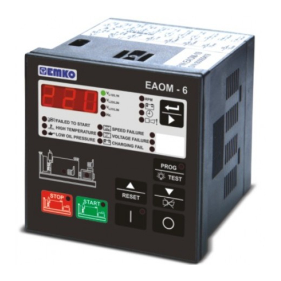
EAOM-6
Automatic Generator Start
Controller with Metering,
96x96 DIN Size
- Automatic engine start / stop
- Automatic shutdown on fault condition
- LED status and fault indication
- Alternator voltages and frequency measurement and monitoring
- Battery voltage measurement and monitoring
- Simple push-button controlled operation
- Over / under speed warning and shutdown
- Remote start / stop input
- Three user configurable inputs
- Provides charge alternator excitation current
- Two configurable relay outputs
- Speed sensing from alternator frequency or magnetic pickup
- Preheat feature
- Fully programmable
- RS-232 communication port
- Standard modem communication
-
Monitors
Alternator voltages and frequency
Battery charging
Engine RPM
-
Controls
Engine fuel supply or engine stopping
Starter motor
Over / Under speed
-
Fail Monitoring
Engine temperature
Oil pressure
Over / Under speed
Voltage fail
EAOM-6 SOFT
PC Communication Software for
Programming and Remote Monitoring
Battery voltage
Engine running time
Engine Power
Preheat
Alarm horn
Charging alternator
Emergency stop
Low battery voltage
Weak battery alarm
Instruction Manual. ENG EAOM-6 02 V00 07/07
Advertisement
Table of Contents

Related Manuals for EMKO EAOM-6


Summary of Contents for EMKO EAOM-6
- Page 1 Engine fuel supply or engine stopping Preheat Starter motor Alarm horn Over / Under speed Fail Monitoring Engine temperature Charging alternator Oil pressure Emergency stop Over / Under speed Low battery voltage Voltage fail Weak battery alarm Instruction Manual. ENG EAOM-6 02 V00 07/07...
- Page 2 ABOUT INSTRUCTION MANUAL Instruction manual of EAOM-6 consists of two main sections. Explanation of these sections are below. Also, there is another section which include technical specifications of the device. All titles and page numbers in instruction manual are in “CONTENTS” section. User can reach to any title with section number.
-
Page 3: Table Of Contents
4.2 CABLE CONNECTION BETWEEN RS-232 TERMINAL OF THE DEVICE AND MODEM 4.3 PC INTERFACE 4.3.1 TECHNICAL SPECIFICATIONS 4.3.2 INSTALLATION INSTRUCTIONS 4.3.2.1 MINIMUM SYSTEM REQUIREMENTS 4.3.3 INSTALLING EAOM-6 SOFTWARE 4.3.4 USING OF EAOM-6 COMMUNICATION SOFTWARE 4.3.5 DESCRIPTION 4.3.6 OBSERVATION WINDOW 4.3.7 OPERATOR PARAMETERS WINDOW 4.3.8 TECHNICIAN PARAMETERS WINDOW 4.3.9 MAIN MENU 4.3.9.1 FILE... - Page 4 5.2 CHANGING and SAVING OPERATOR PARAMETER VALUE 5.3 CHANGING and SAVING TECHNICIAN PARAMETER VALUE 6. LAMP TEST............................Page 7. OPERATION............................Page 7.1 FRONT PANEL DESCRIPTION 7.2 DISPLAY MODE INDICATORS 7.3 STARTING THE ENGINE 7.4 STOPPING THE ENGINE 8.COMMISSIONING..........................Page 9. FAULT FINDING..........................Page 9.1 FAULT INDICATIONS 9.1.1 FAILED TO START LED...
- Page 5 EU DECLARATION OF CONFORMITY Manufacturer Company Name : Emko Elektronik A.Þ. Manufacturer Company Address: DOSAB, Karanfil Sokak, No:6, 16369 Bursa, Turkiye The manufacturer hereby declares that the product conforms to the following standards and conditions. Product Name Electrical control equipment for generating sets...
-
Page 6: Preface
1. PREFACE These products provide control and protection in the operation of a generator set. The units allow starting and stopping of the engine and indicates status and fault conditions. The unit monitors: Engine temperature Oil pressure Charging alternator Over / Under speed Voltage fail Emergency stop Low battery voltage... -
Page 7: General Specifications
BUTTONS 1.2 Warranty EMKO Elektronik warrants that the equipment delivered is free from defects in material and workmanship. This warranty is provided for a period of two years. The warranty period starts from the delivery date. This warranty is in force if duty and responsibilities which are determined in warranty document and instruction manual performs by the customer completely. -
Page 8: Installation
Carefully unpack the unit and check for damage to the unit or to the cables supplied. Retain the packing in case of future need, e.g. returning the unit for calibration. Check the contents, as follows: • One EAOM-6 unit. • Operating Manual. • Screw fixings. -
Page 9: General Description
2.1 General Description Front Panel IP54 Protection NEMA4X Mounting holes 2.2 Dimensions 106mm 13mm 96mm 2.3 Panel Cut-Out 92mm... -
Page 10: Environmental Ratings
2.4 Environmental Ratings Operating Conditions Operating Temperature : -25°C to 70°C Max. Operating Humidity : 90% Rh (non-condensing) Altitude : Up to 2000m. Forbidden Conditions: Corrosive atmosphere Explosive atmosphere Home applications (The unit is only for industrial applications) 2.5 Panel Mounting 1. -
Page 11: Installation Fixing Screws
2.6 Installation Fixing Screws The unit is designed for panel mounting. Fixing is done by two screw fixings 1.Insert the unit in the panel cut-out from the front side. 2.Insert the fixings through the mounting holes and tighten the fixing screws to secure the unit against the panel. -
Page 12: Electrical Wirings
3. ELECTRICAL WIRINGS 3.1 Terminal Layout and Connection Instructions Magnetic Pickup (Max. 10kHz) - BAT GENERATOR VOLTAGE MAXIMUM ~300V (Ph - N) BATTERY VOLTAGE 12Vdc (8-16Vdc) 24Vdc (16-32Vdc) Ensure the position of "Power supply position switch" is in the correct position according to the battery voltage (12 V or 24 V Only qualified personnel and trained technicians should work on this equipment. -
Page 13: Electrical Wiring Diagram
3.2 Electrical Wiring Diagram 3.2.1 1-Phase Wiring Diagram GENERATOR 14 17 GENERATOR VOLTAGE 18 26 27 19 20 21 22 23 24 25 4 Magnetic Pickup FUEL/ (up to 10kHz) START STOP RELAY RELAY CHARGE STARTER D+(W.L) GEN. BATTERY NEGATIVE MUST BE GROUNDED 3.2.2 3-Phase Wiring Diagram GENERATOR LOAD... - Page 14 Table 3.1 shows the connections and recommended cable sizes. Table 3.2 describes the functions of the connections. Table 3.1 Unit wiring Description Cable Size (mm) Notes Max. 12A@24 V Output to start solenoid Positive battery supply input Supplies external solenoids Max.
- Page 15 17 not used on single phase applications. Charge generator failure input. It can be used to detect when engine has started. The EAOM-6 connection replaces the usual charge indicator lamp. It supplies current to the rotor coil from the battery until the engine is running.
-
Page 16: Rs-232 Serial Interface, Programming The Device Over Pc Or Modem
4.RS-232 SERIAL INTERFACE, PROGRAMMING THE DEVICE OVER PC OR MODEM 4.1 Cable Connection Between RS-232 Terminal of the Device and PC EAOM-6 9 pin D connector 9 pin D connector female male White Brown Green Standard communication cable 4.2 Cable Connection Between RS-232 Terminal of the Device and Modem... -
Page 17: Pc Interface
4.3.5 Description EAOM-6 unit communicates with the PC using RS-232 communications. The PC software allows the EAOM-6 unit’s parameters and status information to be displayed on the PC screen. Operator and Technician parameters can be viewed. Parameters are password protected. -
Page 18: Observation Window
4.3.6 Observation Window In this window the values listed below can be observed. Measurement Values Outputs Generator Voltage Configurable Relay Output 1 & 2 Engine Speed Solenoid Relay Battery Voltage Start Relay Running Time Horn Relay Generator Frequency Maintenance Hour Failures Failed to Start High Temperature... -
Page 19: Operator Parameters Window
4.3.9.2 PROGRAMMING This menu is active only when the Operator or Technician Parameters Window is open. Using this menu allows the user to upload parameters from the EAOM-6 unit to the PC or download from the PC to the EAOM-6 unit. -
Page 20: Settings
4.3.9.3 Settings Communication Port Settings: With this menu, user can determine the serial port configurations of the PC Language: Turkish or English can be selected. 4.3.10 Entering to the Operator Parameters Window Click Operator Parameter tab. Enter the Operator Parameter password. If the password is correct, operator parameters will be viewed. -
Page 21: Entering To The Adjustment Window
'Save' button on Save Dialog Box, all parameters will be saved to the file. 4.3.15 Upload For loading parameters from EAOM-6 unit to PC follow the steps below. If user is in operator parameters window, only operator parameters will be viewed. If user is in Technician Parameters Window, all parameters will be viewed. -
Page 22: Parameters
5. PARAMETERS The unit is extensively programmable through the front panel and via PC software. Definition of Parameter Unit Default Alternator Voltage Lower Limit Alternator Voltage Upper Limit Speed Lower Limit 30.0 75.0 47.0 Speed Upper Limit 30.0 75.0 53.0 Battery Voltage Lower Limit 24.0 Reserved... - Page 23 Definition of Parameter Unit Default Configurable Failure Input-3 0 - Only horn temporary 1 - Only horn permanent 2 - Engine stop 3 - Contactor releaser Observing Time of Configurable Failure Inputs P34.0 - For Configurable Failure Input-1 0 - Observation Continuously 1 - Observation While Engine Running P34.1 - For Configurable Failure Input-2 0 - Observation Continuously...
-
Page 24: Program Functions
5.1 Program Functions 5.1.1 Alternator Voltage P00 Alternator Voltage Lower Limit P01 Alternator Voltage Upper Limit P27 Alternator Voltage Fault Control Delay A fault will be reported if the alternator output voltage goes outside the window defined by the upper and lower limits for more than the time defined as the Alternator Voltage Fault Control Delay (P27). -
Page 25: Stop / Fuel Solenoid Selection
5.1.6 Stop / Fuel Solenoid Selection (P16) This parameter allows the use of either a Stop solenoid or a Fuel solenoid. (See Section 5.1.10 Engine Starting.) If Fuel Solenoid selected, the fuel solenoid will be energised while the engine is running and de- energised to cut off the fuel and stop the engine. -
Page 26: Oil Pressure By-Pass Time
Control On Delay (P26) defines a period during which any fault indications, except High Temperature, will be ignored by the unit. This period begins when the EAOM-6 has detected engine starting and has cut off the drive to the starter motor. -
Page 27: Configurable Inputs
5.1.14 Configurable Inputs Configurable Failure Input-1 (P31) Configurable Failure Input-2 (P32) Configurable Failure Input-3 (P33) A contact closure to 0V on any of these inputs causes the horn to sound for the period programmed by Horn Duration (P08) and lights the appropriate indicator on the panel. The unit can be programmed to respond in one of four ways: 0. -
Page 28: Operator Password
5.2 Changing and Saving Operator Parameter Value When button is Operation Screen L12/L1N pressed, all leds and digits L23/L2N are energised, because L31/L3N prog button is also used as test button. Continue to PROG PROG press the prog buton for 5 RESET RESET TEST... - Page 29 Alternator Voltage L12/L1N Lower Limit L23/L2N Parameter L31/L3N Press button for PROG PROG accessing to the RESET RESET TEST TEST Value Alternator Voltage L12/L1N Lower Limit L23/L2N Value L31/L3N Change the PROG PROG parameter with RESET RESET TEST TEST buttons Alternator Voltage L12/L1N Lower Limit...
-
Page 30: Technician Password
5.3 Changing and Saving Technician Parameter Value When button is Operation Screen L12/L1N pressed, all leds and digits L23/L2N are energised, because L31/L3N prog button is also used as test button. Continue to PROG PROG press the prog buton for 5 seconds, Operator Menu RESET RESET... - Page 31 Alternator Voltage L12/L1N Lower Limit L23/L2N Parameter L31/L3N Press button for PROG PROG accessing to the RESET RESET TEST TEST Value Alternator Voltage L12/L1N Lower Limit L23/L2N Value L31/L3N Change the PROG PROG parameter with RESET RESET TEST TEST buttons Alternator Voltage L12/L1N Lower Limit...
-
Page 32: Lamp Test
6. LAMP TEST When button is pressed, all leds and digits are energised. EAOM - 6 FAILED TO START SPEED FAILURE SPARE-1 HIGH TEMPERATURE VOLTAGE FAILURE SPARE-2 ~ ~ ~ ~ ~ ~ LOW OIL PRESSURE CHARGING FAIL SPARE-3 PROG TEST RESET STOP... -
Page 33: Operation
7. OPERATION 7.1 Front Panel Description Number Comment Multi Function Display. This is used for displaying the electrical measurements during normal operation and editing / inspecting programming parameters in programming mode. Failure Indicators. Detailed information available in Section 9 Green LED lights to indicate that alternator output is available and within the Parameters set b y P00 and P01. -
Page 34: Display Mode Indicators
7.2 Display Mode Indicators Four-digit, seven-segment LED display. This displays the selected parameter from the list alongside. Use the button to select which parameter is to be displayed, as indicated by the adjacent LEDs. The button selects the parameter in sequence, as follows. Note that line voltage readings are prefixed by ‘L’... -
Page 35: Commissioning
8. COMMISSIONING Beware of the high voltages connected to this unit. 1. Check that the unit is correctly wired and that the wiring is of a standard and rating compatible with the system. 2. Check that the correct fuses are fitted. 3. -
Page 36: Fault Finding
To obtain this indication, the engine must have been running for at least the period specified by the Oil Pressure By-Pass Time (P25). If this fault occurs, the EAOM-6 will stop the engine without any Engine Cooling Time (P29). -
Page 37: Emergency Stop Message Led
When the battery voltage falls below the value specified by the Battery Voltage Lower Limit (P04). The EAOM-6 measures battery voltage at the EAOM-6 terminals. This failure is indicated with an error messages in EAOM-6. When this failure occurs in EAOM-6, the led with exclamation mark starts to flash and user can see the error messages with the Scroll button 9.1.10 Weak Battery Alarm Message (bAT2) -
Page 38: Programmable Parameters
10. PROGRAMMABLE PARAMETERS The unit is extensively programmable through the front panel and via PC software. Definition of Parameter Default Unit Alternator Voltage Lower Limit Alternator Voltage Upper Limit Speed Lower Limit 30.0 75.0 Speed Upper Limit 30.0 75.0 Battery Voltage Lower Limit 24.0 Reserved 9999... - Page 39 Definition of Parameter Default Unit Observing Time of Configurable Failure Inputs P34.0 - For Configurable Failure Input-1 0 - Observation Continuously 1 - Observation While Engine Running P34.1 - For Configurable Failure Input-2 0 - Observation Continuously 1 - Observation While Engine Running P34.2 - For Configurable Failure Input-3 0 - Observation Continuously 1 - Observation While Engine Running...
-
Page 40: Specifications
11. SPECIFICATIONS Equipment Use : Electrical control equipment for generating sets Housing& Mounting : 96mmx96mmx115mm (excl. 13mm clips) Panel Cut-Out : 92 mm x 92 mm Protection : NEMA 4X (IP54 at front panel, IP20 at rear side). Weight : Approximately 0.7 Kg. Environmental Ratings : Standard, indoor at an altitude of less than 2000 meters with non-condensing humidity...
Need help?
Do you have a question about the EAOM-6 and is the answer not in the manual?
Questions and answers