Table of Contents
Advertisement
Quick Links
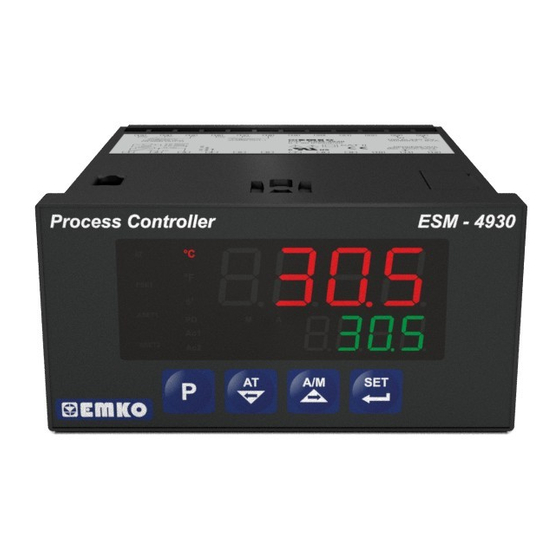
ESM-4930 96 x 48 1/8 DIN
Universal Input PID Process Controller
- 4
digits process (PV) and
- Universal process input
- Dual or multi point calibration for
- Configurable ON/OFF, P, PI, PD ve PID control forms
- Adaptation of PID coefficients to the system with Auto-tune and
Self-tune
- Manual/Automatic mode selection for control outputs
- Bumpless transfer
- Programmable heating, cooling and alarm functions for control
outputs
4 digits process set (SV) display
Z
(TC, RTD, mV
, V
Z
Voltage / Current input
Instruction Manual. ENG ESM-4930 02 V05 04/08
Z
Z
, mA
)
Advertisement
Table of Contents

Related Manuals for EMKO ESM-4930


Summary of Contents for EMKO ESM-4930
- Page 1 - Configurable ON/OFF, P, PI, PD ve PID control forms - Adaptation of PID coefficients to the system with Auto-tune and Self-tune - Manual/Automatic mode selection for control outputs - Bumpless transfer - Programmable heating, cooling and alarm functions for control outputs Instruction Manual. ENG ESM-4930 02 V05 04/08...
- Page 2 ABOUT INSTRUCTION MANUAL Instruction manual of ESM-4930 process controller consists of two main sections. Explanation of these sections are below. Also, there are other sections which include order information and technical specifications of the device. All titles and page numbers in instruction manual are in “...
-
Page 3: Table Of Contents
3.5.4 PROCESS INPUT CONNECTION OF 3-WIRE TRANSMITTERS WITH CURRENT OUTPUT 3.5.5 CONNECTION OF TRANSMITTERS WITH VOLTAGE OUTPUT TO PROCESS INPUT 3.6 GALVANIC ISOLATION TEST VALUES OF ESM-4930 PROCESS CONTROLLER 4.CONNECTION WIRINGS FOR OUTPUTS IN ESM-4930 PROCESS CONTROLLER...... Page 4.1 PROCESS OUTPUT (SSR DRIVER OUTPUT) CONNECTION 4.2 ALARM OUTPUT -1 RELAY CONNECTION... - Page 4 EU DECLARATION OF CONFORMITY Manufacturer Company Name : Emko Elektronik A.S.. Manufacturer Company Address: DOSAB, Karanfil Sokak, No:6, 16369 Bursa, Turkiye The manufacturer hereby declares that the product conforms to the following standards and conditions. Product Name : Process Controller...
-
Page 5: Preface
Some application fields and an applications which they are used are below: Application Fields Application Glass PID Process Control Plastic Petro-Chemistry Textile Automative Machine production industries 1.1 General Specifications ESM-4930 Standard Universal Supply Input 100-240 V , 50/60Hz Power Supply Input Low Voltage (optional) Supply Input 50/60Hz ,24V Universal Process Input... -
Page 6: Ordering Information
1.2 Ordering Information All order information of ESM-4930 are BC D FG HI ESM-4930 given on the table at left. User may form (96x48 1/8 DIN) 01 02 appropriate device configuration from information and codes that at the table and Supply Voltage convert it to the ordering codes. -
Page 7: Warranty
1.3 Warranty EMKO Elektronik warrants that the equipment delivered is free from defects in material and workmanship. This warranty is provided for a period of two years. The warranty period starts from the delivery date. This warranty is in force if duty and responsibilities which are determined in warranty document and instruction manual performs by the customer completely. -
Page 8: Installation
2.Installation Before beginning installation of this product, please read the instruction manual and warnings below carefully. In package , - One piece unit - Two pieces mounting clamps - One piece instruction manual A visual inspection of this product for possible damage occured during shipment is recommended before installation. -
Page 9: General Description
Panel surface IP65 protection (maximum thickness 15mm / 0.59 inch) NEMA 4X 2.2 Dimensions Maximum 15 mm / 0.59 inch ESM- ESM-4930 Process Controller °C °F PSET ASET1 ASET2 96mm / 3.78 inch 10.5 ± 1 mm /0.41 inch 76mm / 2.99 inch... -
Page 10: Panel Cut-Out
2.3 Panel Cut-Out 129 mm / 5.08 inch (min) 92mm / 3.62 inch... -
Page 11: Environmental Ratings
2.4 Environmental Ratings Operating Conditions Operating Temperature 0 to 50 °C Max. Operating Humidity : Rh (non-condensing) Altitude Up to 2000m. Forbidden Conditions: Corrosive atmosphere Explosive atmosphere Home applications (The unit is only for industrial applications) 2.5 Panel Mounting 1-Before mounting the device in your panel, make sure that the cut- out is of the right size. -
Page 12: Installation Mounting Clamp
2.6 Installation Mounting Clamp The unit is designed for panel mounting. 1-Insert the unit in the panel cut- out from the front side. 2- Insert the mounting clamps to the holes that located top and bottom sides of device and screw up the fixing screws until the unit completely immobile within the panel... -
Page 13: Electrical Wirings
3.Electrical Wirings You must ensure that the device is correctly configured for your application. Incorrect configuration could result in damage to the process being controlled, and/or personal injury. It is your responsibility, as the installer, to ensure that the configuration is correct. Parameters of the device has factory default values. -
Page 14: Electrical Wiring Diagram
3.2 Electrical Wiring Diagram Electrical wiring of the device must be the same as ‘Electrical Wiring Diagram’ below to prevent damage to the process being controlled and personnel injury. Universal Process Input (TC, RTD, Voltage / Current) Sensor or Transmitter Standard Process Output Supply Voltage SSR Driver Output... -
Page 15: View Of The Labels
3.3 View of the Labels 5A@250VV 5A@250VV 100 to 240 VV ALARM OUT-1 PROCESS OUT 50/60Hz - 6VA (ALARM OUT-2) P/N : ESM-4930 CAT II 0 to 50mV 0 to 10V 0 to 20mAZ PROCESS OUT SSR DRIVER OUT. Pt-100 Max. -
Page 16: Connection Of Device Supply Voltage Input
3.4 Connection of Device Supply Voltage Input Low Voltage 24 V Universal Supply Voltage Connection Supply Voltage Input Note-2 External External Fuse Fuse (24V : 1 A (1 A (24V : 1 A Power Power Supply Supply Switch Switch Supply Voltage Supply Voltage 100 - 240 V (-15%;+10%) 50/60Hz... -
Page 17: Process Input Connection
3.5 Process Input Connection 3.5.1 TC (Thermocouple) Connection Connect the wires with the polarity as shown in the figure left. Always use compensation wire corresponding to the thermocouple used. If present, the shield must be connected to a proper ground. Input resistance is greater than 10M W 3.5.2 RTD Connection Pt-100... -
Page 18: Process Input Connection Of Serial Transmitters With Current Output (Loop Powered)
3.5.3 Process Input Connection of Serial Transmitters with Current Output (Loop Powered) Transmitter connection by using supply Transmitter connection by using external supply voltage on the device voltage source. Transmitter Transmitter External Power Supply Note-1 15 V ±10% 15 V ±10% Maks. -
Page 19: Connection Of Transmitters With Voltage Output To Process Input
3.5.5 Connection of Transmitters with Voltage Output to Process Input Transmitter connection by using supply Transmitter connection by using external supply voltage on the device voltage source. mV, VZ mV, VZ External Power Supply Note-1 15 V ±10% 15 V ±10% Transmitter Transmitter... -
Page 20: Connection Wirings For Outputs In Esm-4930 Process Controller
4. Connection Wirings for Outputs in ESM-4 Process Controller 4.1 Process Output ( SSR Driver Output ) Connection Device Last Control Element (SSR) Max. , 15mA Fuse Load Fuses must be selected according to the applications. 4.2 Alarm Output-1 Relay Connection Device T Fuse Last Control Element... -
Page 21: Process Output Or Alarm Output-2 Relay Connection
4.3 Process Output or Alarm Output-2 Relay Connection Device T Fuse Last Control Element (Contactor) Fuse Load Fuses must be selected according to the applications. -
Page 22: Definition Of Front Panel And Accessing To The Parameters
(for Process Output) LED Fahrenheit Unit Led indication of Automatic Operation LED indication of (for Process Output) LED units other than °C and °F Process Controller ESM-4930 ESM- LED indication of °C AT , Autotune Displays Process is active Value (PV) and °F... -
Page 23: Observation Of Software Revision On The Bottom Display When Power Is On
5.2 Observation of Software Revision on the Bottom Display When Power Is On When the power is applied to the device all led indicators and display segments are momentarily illuminated for testing. Software revision number of the controller is momentarily illuminated on the bottom display. ESM-4930 Process Controller ESM- °C °F... -
Page 24: Adjustment Of Process And Alarm Set Values
5.3 Adjustment of Process and Alarm Set Values Operation Screen Process Set Screen °C °C °F °F PSET PSET ASET1 ASET1 ASET2 ASET2 When SET button is pressed, PSET Set value can be Press Menu button to changed with LED flashes. “PSET” is shown on exit without saving increment and top display and process set value is... - Page 25 Alarm-2 Set Screen parameter in PCnF °C menu is , this parameter °F ASET2 Led flashes PSET is accessible. If it is , this ASET1 parameter is not accessible and device turns to main operation ASET2 Set value can be changed screen.
-
Page 26: Easy Access Diagram For Program Parameters
5.4 Easy Access Diagram For Program Parameters Main Password Operation Entering °C °C °C °C °F Screen °F °F Screen °F PSET PSET PSET PSET ASET1 ASET1 ASET1 ASET1 ASET2 ASET2 ASET2 ASET2 Press “P” button for Press SET/OK button for Confirm the accessing to the password with... - Page 27 5.4 Easy Access Diagram For Program Parameters Note-3 PCnF ALn1 ALn2 Genn Password °C Menu °C Menu °C Menu °C Menu °C Menu °F °F °F °F °F PSET PSET PSET PSET PSET ASET1 ASET1 ASET1 ASET1 ASET1 ASET2 ASET2 ASET2 ASET2 ASET2...
-
Page 28: Accessing To The Technician Menu
5.5 Accessing to the Technician Menu The parameters have been divided into groups according to their functions. Every group has a title and firstly user must determine the title (menu) for accessing to the parameters. Refer to the parameters section for detailed information about parameters. Operation Screen Technician Menu Entering Screen °C... - Page 29 DiSP List Menu °C It defines which parameter °F PSET will be shown on top and ASET1 bottom display ASET2 Technician can access to Technician can access to the the following menu by former menu by pressing pressing menu changing menu changing back button.
- Page 30 ALn2 CONF Menu This parameter is accessible if °C Configuration parameters parameter in PCnF °F PSET of ALARM -2 Output menu is ASET1 ASET2 Technician can access to the Technician can access to former menu by pressing the following menu by menu changing back button.
-
Page 31: Changing And Saving Parameters
5.6 Changing and Saving Parameters Example-1 : To change Process Input Type parameter Process Input Type parameter is in PýnP Conf” menu, so PýnP ConF menu must be “ accessed firstly in order to reach parameter. Operation Screen Technician Menu Entering Screen °C °C °F... - Page 32 DiSP List Menu °C It defines which parameter °F PSET will be shown on top and ASET1 bottom display ASET2 Technician can access to the Technician can access to former menu by pressing the following menu by menu changing back button. pressing menu changing next button PINP CONF Menu...
- Page 33 TC Input Type Selection °C °F PSET ASET1 ASET2 PINP CONF Menu Press Set button to access When Menu button is pressed, to the next parameter technician can access to the menu pages. °C °C °F °F PSET PSET ASET1 ASET1 ASET2 ASET2...
- Page 34 Example-2 : Changing operation form from “Auto” “Manual” and adjustment of % output. If operation form is Auto (Close-Loop Control) and there is an output with PID or ON/OFF control form, device controls the process outputs by calculating the % output values automaticaly.
- Page 35 Alarm-1 Set Screen °C ASET1 Led flashes °F PSET ASET1 ASET2 Press SET button This parameter is accessible if Alarm-2 Set Screen °C parameter in PCnF ASET2 Led flashes °F PSET menu is . It is not accessible if Parameter ASET1 ASET2 Press SET button...
- Page 36 Example-3 : To change proportional band parameter Proportional band parameter is in Pýd Conf” menu, so “Pýd Conf” menu must be accessed “ firstly. Operation Screen Technician Menu Entering Screen °C °C °F °F PSET PSET ASET1 ASET1 ASET2 ASET2 When “P”...
- Page 37 DiSP List Menu °C It defines which parameter °F PSET will be shown on top and ASET1 bottom display ASET2 Technician can access to the Technician can access to former menu by pressing the following menu by menu changing back button. pressing menu changing next button PINP CONF Menu...
- Page 38 Integral Time °C °F PSET ASET1 ASET2 Pid CONF Menu Press Set button to access When Menu button is to the next parameter pressed, technician can access to the menu pages. °C °C °F °F PSET PSET ASET1 ASET1 ASET2 ASET2 Derivative Time For accessing to the other...
- Page 39 ZVoltage / Current Input Calibration Type Selection parameter Example-4 : To change “ PýnP Conf” menu Parameter is in “PýnP ConF” menu. For accessing to this parameter, technician must access to “PýnP ConF” menu firstly. In this example, changing input type of a device from Z oltage / Current and dual point calibration selection is shown.
- Page 40 DiSP List Menu °C It defines which parameter °F PSET will be shown on top and ASET1 bottom display ASET2 Technician can access to Technician can access to the the following menu by former menu by pressing pressing menu changing menu changing back button.
- Page 41 ZVoltage / Current Input °C Calibration Type °F PSET Selection ASET1 ASET2 Parameter can be changed with increment and decrement buttons Z Voltage / Current °C Input Calibration Type °F PSET Selection ASET1 ASET2 Press Set button to confirm the value and access to the next parameter Minimum value for °C...
-
Page 42: Parameters
6. Parameters Parameters are divided into two groups. They are Process / Alarm Set parameters and Technician parameters. Technician parameters are grouped into subgroups according to their functions. The subgroups are named as menu pages. 6.1 Process / Alarm SET Parameters Process set value Process set value can be adjusted from minimum value of set scale... -
Page 43: Technician Parameters
6.2 Technician Parameters 6.2.1 Selection of PID Tune and Operation Form TUNE SELECTION By selecting one of the methods below, device can determine the PID parameters. Device operates according to the defined PID parameters Auto tune (Limit Cycle Tuning) operation Self tune (Step Response Tuning) operation Auto-Self Tune Self Tune operation is performed, if the conditions are... - Page 44 TUNE METHODS There are 2 different methods for determining PID parameters by the device. These Auto tune ( Limit Cycle Tuning) and Self Tune (Step Response Tuning) methods. Determining of PID parameters with Auto Tune is started in these conditions : By the user in any time, By the device when system gets unstable and starts oscillation If process value is out of...
- Page 45 Auto Tune (Limit Cycle Tuning) operation ; if heating or heating-cooling function and PID control form is selected, process control output runs according to heating if cooling function and PID control form is selected, process control output runs according to cooling . Control is unstable While Atun Process...
- Page 46 PID coefficients are determined Process and system becomes stable. Value Process Set Value ( Start Value + [ ( Set - Start Value) ] Stun Start Value Time Process Output 100% If cooling function and PID control form is selected for the system; If set value is less than process value, process output becomes active till to the Temperature - [( Temperature - Set ) / 2] value.
- Page 47 Self Tune operation is finished without any problem, device saves new PID parameters to memory and runs. It changes parameter. parameter is it is changed to , if it is , it is changed Self Tune operation is interrupted at half, PID parameters and parameter are not changed, device continues to run with former PID parameters.
-
Page 48: Function Selection For Top And Bottom Display
BUMPLESS TRANSFER Process output value in manual control is not taken into consideration while passing from manual control to automatic control. New control output that is measured in automatic control is applied to process output. Last %output value is taken output value of manual control and manual control continues while passing from automatic control to manual control. -
Page 49: Process Input Type And Relevant Parameters With Process Input
6.2.3 Process Input Type and Relevant Parameters with Process Input Defines the process input type. TC input type selection RTD input type selection ZVoltage / Current input type selection. Defines type and scale of the thermocouple for TC input. It is active if TC input type is selected. - Page 50 Defines type and scale of sensor for RTD input. It is active if RTD input is selected. PT-100 ( -200°C ; 650°C ) or ( -328°F ; 1202°F) PT-100 ( -199.9°C ; 650.0°C ) or ( -199.9°F ;999.9°F) Defines input range and scale of Voltage / Current input.It is active if Voltage / Current is selected.
- Page 51 Process Set value Po10 Po11 Po09 Po12 Po08 Po13 Po07 Po14 Po15 Po06 Po16 Po05 Po04 Po03 Po02 Po01 Po00 = 0 3.125 6.25 9.375 12.5 15.625 18.75 21.825 28.125 31.25 34.375 37.5 40.625 43.75 46.875 3.125 3.125 3.125 3.125 3.125 3.125 3.125 3.125 3.125 3.125 3.125 3.125 3.125 3.125 3.125 3.125 0-50 mV range are divided into 16 egual parts.
-
Page 52: Pid Configuration Parameters
6.2.4 PID Configuration Parameters If any output is configured as heating PID ; parameters are accessible If no output is configured as PID ; Only parameters are accessible in PID CONF menu. PROPORTIONAL BAND ( 0.0% , 999.9% ) Full Scale ( ) %. - Page 53 MÝNÝMUM CONTROL OUTPUT ( 0.0% , It is % of minimum output. Even as a result of the PID calculation device calculates the %output value less than this parameter, heating or cooling output is active minimum for OLL parameter. CALCULATED OUTPUT GIVEN OUTPUT...
- Page 54 ANTI-RESET WINDUP (0, SCALE HIGH POINT) While PID operation is running if <= process value <= condition is true, integral value is calculated. If the condition is not true, integral value is not calculated and last calculated integral value is used. Scale High Point : Maximum process input value in Pt-100 and Tc inputs 9999 for fixed dual point calibration used inputs,...
- Page 55 PID OUTPUT OFFSET (FOR HEATING PID 0.0%, 100.0%) (FOR COOLING PID -100.0%, 0.0%) This parameter is added to “Output %” which is calculated at the end of the PID. Process Output 100% PoFS = 5.0% PoFS = -5.0% Process Value OUTPUT OFFSET RELATED TO PID SET (FOR HEATING PID 0.0%, 100.0%) (FOR COOLING PID -100.0%, 0.0%)
- Page 56 PROCESS VALUE STABILIZATION ( 1, SCALE HIGH POINT) It is used for controlling if process value oscillates or not when Parameter is <= Process Value <= condition is not true and process value starts to oscillate (as shown in the diagram). If parameter is ,then parameter is selected...
- Page 57 > 0 Process Output 100% Process Value Set Value Cooling Set Value < 0 Process Output 100% Process Value Cooling Set Value Set Value SENSOR BREAK OUTPUT VALUE (FOR HEATING PID 0.0%, 100.0%) (FOR COOLING PID -100.0%, 0.0%) When sensor breaks, controlling of the process can continue by entering %output value to parameter.
-
Page 58: Process Output Configuration Parameters
6.2.5 Process Output Configuration Parameters It determines if Process Output ( SSR Driver Output ) and Alarm Output-2 operates together or not. Process Output (SSR Driver Output) and Alarm Output-2 operates separate Process Output (SSR Driver Output) and Alarm Output-2 operates together. -
Page 59: Alarm Output-1 Configuration Parameters
6.2.6 ALARM Output-1 Configuration Parameters It determines logic output function for Alarm Output-1 Alarm output Manual / Automatic data output Sensor break alarm output Output is active when the process value is out of the band which is defined with minimum value of operating scale And maximum value of operating scale It determines alarm type for Output-1. - Page 60 Deviation band alarm Alarm Output Process Process Set + Alarm Set Process Set - Alarm Set Process Value Deviation range alarm Alarm Output Process Process Set + Alarm Set Process Set - Alarm Set Process Value Alarm- 1 hysteresis value. it can be adjusted from 0% to 50% of process input scale ) It is active if logic output function of Alarm Output-1 is alarm output.
-
Page 61: Alarm Output-2 Configuration Parameters
6.2.7 ALARM Output-2 Configuration Parameters “Aln2 Conf” Menu is accessible if parameter in “PCnF ConF” is It determines logic output function for Alarm Output-2 Alarm output Manual / Automatic data output Sensor break alarm output Output is active when the process value is out of the band which is defined with minimum value of operating scale And maximum value of operating scale It determines alarm type for Output-2. - Page 62 Deviation band alarm Alarm Output Process Process Set + Alarm Set Process Set - Alarm Set Process Value Deviation range alarm Alarm Output Process Process Set + Alarm Set Process Set - Alarm Set Process Value Alarm- 2 hysteresis value. it can be adjusted from 0% to 50% of process input scale ) It is active if logic output function of Alarm Output-2 is alarm output.
-
Page 63: General Parameters
6.2.8 General Parameters Minimum value for process set and alarm set values. It is named as low limit of set scale. It can be adjusted from low limit of input selected with parameter parameter. Please refer to Section 6 .2.3 Process Input Type and Relevant Parameters with Process Input for parameter Maximum value for process set and alarm set values. -
Page 64: Technician Password
6.2.9 Technician Password It is used for accessing to the technician parameters. It can be adjusted from 0 to 9999. If it is ; there is no password protection while entering to the technician parameters. If it is different from “ 0” and user wants to access to the technician parameters;... - Page 65 Failure Messages in ESM- 4930 Process Controllers 1 - Sensor failure in analogue inputs. Sensor connection is wrong or °C there is no sensor connection. °F PSET ASET1 ESM- ASET2 °C 2 - If value on top display blinks : If analogue input value is less than °F PSET minimum value of operating scale...
- Page 66 5 - If tuning operation can not be completed in 8 hours, AT led starts to °C °F blink.Blinking can be canceled by pressing Enter button. PSET ASET1 ASET2 For details on parameters, refer to Section 6.2.1 6 - If user does not do anything for 120 °C °C °F...
-
Page 67: Specifications
8. Specifications Device Type : Process Controller Housing&Mounting : 96mm x 48mm x 86.5mm 1/8 DIN 43700 plastic housing for panel mounting. Panel cut-out is 92x46mm. Protection Class : NEMA 4X (IP65 at front, IP20 at rear). Weight : Approximately 0.21 Kg. Environmental Ratings : Standard, indoor at an altitude of less than 2000 meters with none condensing humidity.
Need help?
Do you have a question about the ESM-4930 and is the answer not in the manual?
Questions and answers