Table of Contents
Advertisement
Quick Links
Built with Anthro-DNA™
For Warranty visit: www.ergotron.com/warranty
For Service visit: www.ergotron.com
For local customer care phone numbers visit: http://contact.ergotron.com
• 09/18
300-5642-00 rev. C
A S S E M B LY I N S T R U C T I O N S
Steve's Station™
Advanced
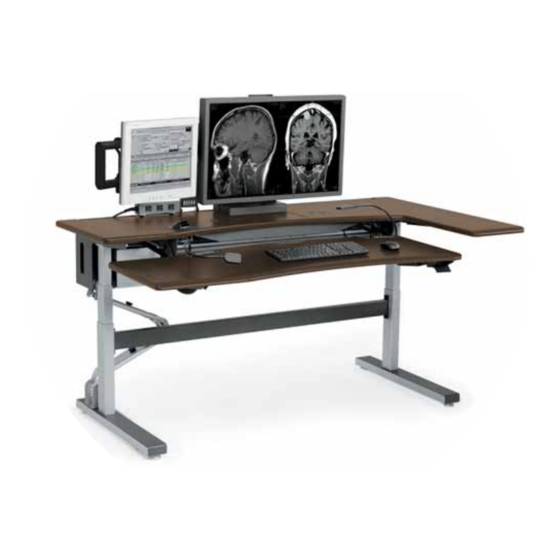
Steve's Station Advanced
Shown in LD + 1 Confi guration
1
Advertisement
Table of Contents

Subscribe to Our Youtube Channel
Related Manuals for Ergotron Steve's Station Advanced


Summary of Contents for Ergotron Steve's Station Advanced
- Page 1 A S S E M B LY I N S T R U C T I O N S Steve's Station™ Advanced Steve's Station Advanced Shown in LD + 1 Confi guration For Warranty visit: www.ergotron.com/warranty For Service visit: www.ergotron.com For local customer care phone numbers visit: http://contact.ergotron.com • 09/18 300-5642-00 rev. C...
- Page 2 GETTING STARTED W E LCO M E PA R T S L I S T Before beginning installation of your Steve's Station Thank you for purchasing Steve's Station! table, check that you've received the proper kits. Con- tents for each kit are listed in the assembly step where TO O L S they're used.
- Page 3 S T E P 2 ONCE YOU’RE IN THE ROOM Determine the location and orientation of the assembled table. Roll the table into place. Leave about two feet behind the table so you have room to move during assembly.
- Page 4 S T E P 4 INSTALL THE MONITOR BOOM Locate the box containing the monitor boom assembly (part #500- 1112-03). Unpack the assembly. From the parts kit, grab the four M6X14 Flat-hd Screws (325-5435-00) from the kit. Locate the zip tie holding the small metal plate to the base of the Monitor Easy Track.
- Page 5 S T E P 6 INSTALL THE UPPER CABLE CARRIER Locate the Upper Cable Carrier assembly (part #835-5685-03) and inventory its contents. It should contain: 1 ea Upper Cable Carrier 2 ea 10-24 X 1/2 BHS THRD FORM SCREW*BK* (325-5464-00) ...
- Page 6 S T E P 7 INSTALL THE LOWER CABLE CARRIER Locate the Cable Carrier assembly (part #835-5465-61) and inventory its contents. It should contain: 1 ea Cable Carrier 835-5465-61 2 ea 10-24x1/2" socket-head cap screws (325-5598-00) Determine which side of the table will receive the carrier.
- Page 7 S T E P 8 TEST THE TABLE Make sure the table is plugged in and the switch on the power bar is on. Remove the protective covers on the task lights. Turn on the task lights and check the dimmer controls. ...
- Page 8 The system will return to normal operation (and give a short blink) after 5 seconds of inactivity on the keys. © 2018 Ergotron, Inc. All rights reserved. All trademarks are the property of their respective companies. Anthro is a registered trademark and brand of Ergotron Inc. Anthro-DNA is a trademark of Ergotron Inc. • 09/18...
Need help?
Do you have a question about the Steve's Station Advanced and is the answer not in the manual?
Questions and answers