Table of Contents
Advertisement
LFS-PM Series Live Focus System Operating Manual
LFS-PM Series Live Focus System
Operating Manual V2.0
Read this manual before operation
The content include of electric connections and operating steps
Read the manual to ensure electric connection
RuiDa Technology Co., Ltd
Addr:
1TH FLOOR,5TH BUILDING,NANYOU TIANAN
INDUSTRIAL ZONE,SHENZHEN
Tel:
0755--26066687
Fax:
0755--26982287
E-mail:
sales@rd-acs.com
Web:
www.rd-acs.com
I
Advertisement
Table of Contents

Related Manuals for Ruida Technology LFS-PM Series


Summary of Contents for Ruida Technology LFS-PM Series
- Page 1 LFS-PM Series Live Focus System Operating Manual Read this manual before operation The content include of electric connections and operating steps Read the manual to ensure electric connection LFS-PM Series Live Focus System Operating Manual V2.0 RuiDa Technology Co., Ltd...
- Page 2 LFS-PM Series Live Focus System Operating Manual COPY RIGHT RuiDa technology keep the right of the following: 1. Ruida technology owns all the patent right and property right of the products. Ruida will preserve the right to pursue legal actions against copying , producing this product.
-
Page 3: Table Of Contents
LFS-PM Series Live Focus System Operating Manual Contents CHAPTER 1 INTRODUCTION ....................1 PRODUCT INTRODUCTION ..................1 PRODUCT MODEL INTRODUCTION ............... 1 CHAPTER 2 FUNCTIONS ......................2 TOUCH SCREEN ......................2 CONTROL FUNCTIONS ..................... 3 2.2.1 Main Interface Introduction ..................3 2.2.2 Parameter Setting ..................... - Page 4 LFS-PM Series Live Focus System Operating Manual 5.1.2 Upper/Lower Limit Trigger ..................25 5.1.3 Reset Error ......................25 5.1.4 Capacitance Smaller ....................25 5.1.5 Crash Alarm ......................26 5.1.6 Emergency Stop ..................... 26 5.1.7 Too Large Following Error ..................26 5.1.8 Multiple Error ......................
-
Page 5: Chapter 1 Introduction
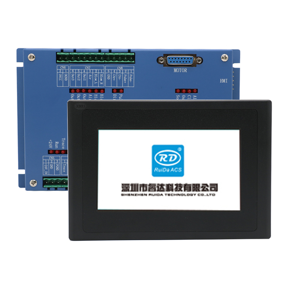
LFS-PM Series Live Focus System Operating Manual Chapter 1 Introduction Product Introduction LFS-PM is automatic distance control system that based on the capacity sensor. This system has a 7.0” or 4.3” TFT touch screen and can display the work status and detecting capacity value. -
Page 6: Chapter 2 Functions
LFS-PM Series Live Focus System Operating Manual Chapter 2 Functions 2.1 Touch Screen This distance controller is included of a 7.0” or 4.3” touch TFT screen. The resolution is 800*480 or 480*272. the laser head work status is displayed in the monitor and parameters can be modified with the monitor. -
Page 7: Control Functions
LFS-PM Series Live Focus System Operating Manual Running Status and Alarm Display Data Display Function Button 7.0” Touch Screen Main interface The communication between the controller and the touch screen monitor is by RS232. If all the electrical connections has been done correctly, when power on the controller, the monitor of the controller will go to the main interface. -
Page 8: Parameter Setting
LFS-PM Series Live Focus System Operating Manual human harm. “±0.1”:modify the distance between the nozzle and the work sheet. Press one time, 0.1mm will increase or decrease. : to control the laser head to move up or move down. If the button is pressed, the laser head will be always moving until the button is released. - Page 9 LFS-PM Series Live Focus System Operating Manual When cutting non-metal, this para is invalid. Rise Height The rising height for laser head during jump motion. When the alarm triggered, the laser head is on the Alarm Height stop height. When the cutting task is finished, the laser head is on Standby Height the position.
-
Page 10: Parameter Management
LFS-PM Series Live Focus System Operating Manual triggered, the motion protection will take affect such as rising the laser head and stop motion. 2.2.3 Parameter Management Parameters management is used to save and restore the parameters of the distance controller. Not everybody can operate this function. There are passwords for user to manage this function. -
Page 11: Calibration
LFS-PM Series Live Focus System Operating Manual 2.2.5 Calibration In the main menu, press “FUNCTION” to go to “CALIBRATION” interface. Calibration is very important for a correct application of the distance controller. If the laser head has stand by for a very long time or the environment has changed a lot, a calibration should be done. -
Page 12: Auxiliary Gas Test
LFS-PM Series Live Focus System Operating Manual Because the capacitor is a sensitive to temperature and humidity of the environment, user should wait 3~5 minutes when power on to let the sensor and amplifier to reach a stable temperature. 2.2.6 Auxiliary Gas Test In the main menu, press “FUNCTION”... -
Page 13: System Time
LFS-PM Series Live Focus System Operating Manual 2.2.8 System Time In the main menu, press the “date and time” to go to modify the date and time. -
Page 14: Chapter 3 Electrical Connection
LFS-PM Series Live Focus System Operating Manual Chapter 3 Electrical Connection 3.1 Interface Of The Distance Controller Take RDC6332M for instance, integrated system wiring diagram as follow: +24V High pressure relay +24V Low pressure relay Pul+ Pul- Motor Driver +24V... - Page 15 LFS-PM Series Live Focus System Operating Manual The auxiliary gas wiring instructions are as follows: When cutting Non-metal (Follow OFF), the air is always controlled. When cutting metal (Follow ON), the punching and cutting gas can be selected by the parameters of the channel blowing.
- Page 16 LFS-PM Series Live Focus System Operating Manual Air control High-pressure solenoid valve solenoid valve Cutting type Gas channel of punching Gas channel of cutting Non-metal Metal High-pressure Parameter setting: If punching is air and cutting is High pressure gas (or Low-pressure).
-
Page 17: Sensor Interface
LFS-PM Series Live Focus System Operating Manual Metal High-pressure The Third Program:3 relay wiring Parameter setting: If punching is low pressure gas and cutting is high pressure gas. When cutting Non-metal (Follow OFF), LFS will control the Air channel outlet all the time. -
Page 18: Cn1
LFS-PM Series Live Focus System Operating Manual 3.1.2 CN1----RS232 Interface SIGNAL DEFINITION DESCRIPTION — PIN 1 Send data — PIN 2 Receive data — PIN 3 3.1.3 CN2----Analog Interface SIGNAL DEFINITION DESCRIPTION — PIN1 AGND Analog GND PIN2 Analog In Analog input Input scale:0—10V... -
Page 19: Cn4
LFS-PM Series Live Focus System Operating Manual Mechanical contact switch Proximity switch wiring instructions as follow: Proximity switch +24V Emergency switch wiring instructions as follow: Mechanical Switch EmStp 3.1.5 CN4----Control Input And Output SIGNAL DEFINITION DESCRIPTION When low level, the LFS will control the... -
Page 20: Cn5
LFS-PM Series Live Focus System Operating Manual PIN4 UpOk Rising up status Low level valid PIN5 DnOk Going down status Low level valid When the laser head crash to the metal PIN6 AlmOut Crash alarm output plate, the AlmOut output 24V. -
Page 21: Motor Control Interface For Servo Mode
LFS-PM Series Live Focus System Operating Manual — — PIN1 Pulse- — — PIN2 Pulse+ — — PIN3 Dir- — — PIN4 Dir+ — — PIN5 To control step motor, differential mode and common-anode mode can be applied. We recommend user to select differential mode . -
Page 22: Hmi Interface
LFS-PM Series Live Focus System Operating Manual 3.1.11 HMI Interface The connection between the distance controller and the displayer is shown as follows: touch screen color of wire read blue brown yellow 3.1.12 USB Interface USB is a U disk interface that used to upgrade the firmware. - Page 23 LFS-PM Series Live Focus System Operating Manual Direction signal indicator. Low level input will turn on the led Blow_H High pressure gas control output. Low level input will turn on the led Blow_L Low pressure gas control output. Low level input will turn on the led Air control output.
-
Page 24: Chapter 4 Test And Run
LFS-PM Series Live Focus System Operating Manual Chapter 4 Test and Run Test and run is based the RDC6332M cutting controller and the control software is Metal Cut. 4.1 Distance Controller Test Before we start the distance controller test and run, the cutting control system and the distance controller should be wired correctly. - Page 25 LFS-PM Series Live Focus System Operating Manual User still can selet the “check follow up ” to be “use delay” and the “check follow” to be “using trigger”. The first operation should be careful. The following step should be noticed: 1) If the drive is servo drive, please set the parameters correctly according to the operating manual of the servo drive.
-
Page 26: Cutting Test
LFS-PM Series Live Focus System Operating Manual Cutting Test Before start a cutting, user should configure the parameters of the machine correctly. please reference to the RDC6332M controller operating manual. Cutting test should follow the steps: Open MetalCut, draw a cutting rectangle with the drawing tools. - Page 27 LFS-PM Series Live Focus System Operating Manual For laser piercing, the motion controller support CW piercing and pulse piercing mode. To set the piercing mode in the user parameters and layer parameters. The piercing time is decided by the piercing times (n) and single piercing time (Ton).
- Page 28 LFS-PM Series Live Focus System Operating Manual Auxiliary test Press the “function” to go to “auxiliary test” page. This used to test the piercing gas and the cutting gas. Laser emission test In the operating panel of the motion controller, press “pulse” to test the laser.
-
Page 29: Chapter 5 Alarm Information
LFS-PM Series Live Focus System Operating Manual Chapter 5 Alarm Information 5.1 Description Of The Alarm During the running, there maybe some alarm happened because of some undesired conditions. The alarm information will be considered and some protection should be executed. -
Page 30: Crash Alarm
LFS-PM Series Live Focus System Operating Manual displayed. There may be the following reasons: Do not do a calibration for a long time or the humidity and temperature has changed a lot. Do a calibration again to clear this fault. -
Page 31: Chapter 6 Installing
LFS-PM Series Live Focus System Operating Manual Chapter 6 Installing 6.1 Size Of The Distance Controller Size Of The Touch Screen 4.3”Touch Screen Size:... -
Page 32: Size Of The Amplifier
LFS-PM Series Live Focus System Operating Manual 7.0”Touch Screen Size: Size Of The Amplifier... -
Page 33: Appendix: Trouble Shoots
LFS-PM Series Live Focus System Operating Manual Appendix: Trouble Shoots FAULT MAIN REASON SOLVED Wiring of DIR+、DIR-、 Reference to the manual to PULSE+、PULSE-is not ensure a right connection correct Parameters of Servo drive is Reference to the servo drive not correct... - Page 34 LFS-PM Series Live Focus System Operating Manual metal sheet sheet. Before calibration, check the During the calibration, up limit positon of the laser head. or down limit triggered Move the laser head away from the limit Check the parameters of the...
- Page 35 LFS-PM Series Live Focus System Operating Manual Thank you for your selection of our production! All the copyright of this manual is owned by Ruida technology. Any person or company can not copy upload and send the manual without Ruida‟s permission.
Need help?
Do you have a question about the LFS-PM Series and is the answer not in the manual?
Questions and answers