Table of Contents
Advertisement
RuiDa Technology Co., Ltd
Addr:
3th
floor,Technology
Avenue,Nanshan
Province,P.R.China
Tel:
0755--26066687
Fax:
0755--26982287
E-mail:
sales@rd-acs.com
Web:
www.rd-acs.com
SHENZHEN RUIDA TECHNOLOGY
Read this manual before operation
The content include of electric connections and operating steps
Read the manual to operate the systems
RDC6445G
Building,NO.,1067
District,Shenzhen
city,Guangdong
RDC6445G Control System manual V1.2
Control System manual
Nanhai
Advertisement
Table of Contents

Related Manuals for Ruida Technology RDC6445G


Summary of Contents for Ruida Technology RDC6445G
- Page 1 RDC6445G Control System manual V1.2 Read this manual before operation The content include of electric connections and operating steps Read the manual to operate the systems RDC6445G Control System manual RuiDa Technology Co., Ltd Addr: floor,Technology Building,NO.,1067 Nanhai...
- Page 2 RDC6445G Control System manual V1.2 COPYRIGHT All rights reserved.You may not reproduce, transmit, store in a retrieval system or adapt thispublication, in any form or by any means, without the prior written permissionof RuiDa, except as allowed under applicable copyright laws. We have identifiedwords that we consider as trademarks.
- Page 3 RDC6445G Control System manual V1.2 CERTIFICATION DECLARATION The product has been certified by the CE (Commutate European) safety certification. It has passed the corresponding conformity assessment procedure and the manufacturer's declaration of conformity, in accordance with the relevant EU directive.
- Page 4 RDC6445G Control System manual V1.2 SAFETY INFORMATION When using this system, please make sure the operation is correct and the usage is safe. Some signs or text will be used to remind you to pay attention to the dangerous matters and some important information.
- Page 5 If any missing parts or damaged parts are found, please contact ruida technology immediately.Do not install or debug the equipment if any obvious damage is found.
-
Page 6: Table Of Contents
RDC6445G Control System manual V1.2 Contents Chapter 1 Overview............................1 1.1 Briefing............................... 2 1.2 Description of Controller Model......................2 1.3 Comparison of Controller Performance.....................2 Chapter 2 Installation Size........................... 5 2.1 Installation Size of MainBoard......................6 2.2 Size of Panel............................6 Chapter 3 Object Pictures and Interfaces....................6 3.1 Object Pictures of MainBoard......................8... - Page 7 RDC6445G Control System manual V1.2 8.5.1 User parameters........................36 8.5.2 Vender parameters........................39 8.5.3 Origin Setting..........................40 8.5.4 Backup parameters........................41 8.5.5 Restore parameters........................42 8.6 Controller setting..........................42 8.6.1 Language........................... 42 8.6.2 Screen origin..........................43 8.6.3 Wireless panel...........................44 8.6.4 IP Setting........................... 44 8.6.5 System Info..........................45...
-
Page 8: Chapter 1 Overview
RDC6445G Control System manual V1.2 Section 1 Overview CONTENTS: Briefing Description of Controller Model Comparison of Controller Performance SHENZHEN RUIDA TECHNOLOGY... -
Page 9: Briefing
RDC6445G Control System manual V1.2 1.1 Briefing RDC6445G system is a new generation system for control of laser engraving and cutting, which is developed by RD Co., Ltd. In addition to high hardware stability, high voltage or static electricity rejection, and friendly 5’’ TFT man-machine display. This system is provided with... - Page 10 RDC6445G Control System manual V1.2 non-interacted non-interacted Copying Common Quick Quick Very Quick Speed Feature Compatibili Support USB Support all USB Support all USB Support disks with disks with disks with disks with different small different different capacities capacity capacities...
- Page 11 RDC6445G Control System manual V1.2 progress bar display Modifi cation Factory/Use r’s para on display Display 128*64, dot 320*240 320*240 320*480 TFT display type display display display Soft Spacing Motion-axl Hard e Feature Spacing Z-axle Linkage Feeding Single Single/double Single/double...
-
Page 12: Chapter 2 Installation Size
RDC6445G Control System manual V1.2 Section 2 Installation Size CONTENTS: Installation Size of MainBoard Size of Panel SHENZHEN RUIDA TECHNOLOGY... -
Page 13: Installation Size Of Mainboard
RDC6445G Control System manual V1.2 2.1 Installation Size of MainBoard The unit of all sizes is millimeter (mm) and the size accurate to 0.1mm (the four holes are symmetrical) Figure 2.2 Size of Panel The unit of all sizes is millimeter (mm) and the size accurate to 0.1mm. -
Page 14: Chapter 3 Object Pictures And Interfaces
RDC6445G Control System manual V1.2 Section 3 Object Pictures and Interfaces CONTENTS: Object Pictures of MainBoard Object Pictures of Panel Electric connection Lamp instruction SHENZHEN RUIDA TECHNOLOGY... -
Page 15: Object Pictures Of Mainboard
RDC6445G Control System manual V1.2 3.1 Object Pictures of MainBoard For more detailed pin description, see the Chapter 4: Description of Interface Signal for MainBoard. Figure: 3.1-1 Object Picture MainBoard SHENZHEN RUIDA TECHNOLOGY... -
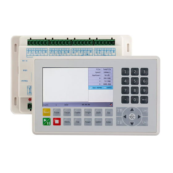
Page 16: Object Pictures Of Panel
RDC6445G Control System manual V1.2 3.2 Object Pictures of Panel Figure: 3.2-1 Object Picture of Panel SHENZHEN RUIDA TECHNOLOGY... -
Page 17: Electric Connection
RDC6445G Control System manual V1.2 3.3 Electric connection Figure 3.3-1 electric connection 3.4 Lamp instruction RDC6445G have fifteen red lamps: LED NUMBER NAME SENSE LED1 LmtX- negative limit indicator LED2 LmtX+ positive limit LED3 LmtY- negative limit LED4 LmtY+ positive limit... - Page 18 RDC6445G Control System manual V1.2 LED8 LmtU+ positive limit LED9 Indication for water protect 1 LED10 Indication for water protect 2 LED11 Ethernet communication LED12 Link Ethernet connection LED13 error in controller hardware LED14 the normal running status LED15 +5V power supply...
- Page 19 RDC6445G Control System manual V1.2 Section 4 Description of Interface Signal for MainBoard CONTENTS: Interface of Main Power Source CN0 Panel Signal-Cable Interface HMI Udisk Interface PC-USB Interface Ethernet Interface General Output Port SHENZHEN RUIDA TECHNOLOGY...
- Page 20 RDC6445G Control System manual V1.2 General Input Port 4-axle Spacing Input Interface CN3/CN4 X/Y/Z/U axle Motor Driver Interface AXIS_X~AXIS_U Laser Power Control Interface CN5/CN6 SHENZHEN RUIDA TECHNOLOGY...
-
Page 21: Interface Of Main Power Source Cn0
RDC6445G Control System manual V1.2 4.1 Interface of Main Power Source CN0 Symbols Definitions 24V power ground (input) +24V 24V power positive (input) This control system employs single 24 power supply. For a certain margin, it is suggested to select 24V/2A power. Besides, this system is... -
Page 22: General Input Port Cn2
RDC6445G Control System manual V1.2 Symbols Definitions Power ground (output) Out2 General output, with the function reserved. Out1 General output, with the function reserved. Status General output for the signal port of running status. If this port is externally connected with the relay, the relay coil is broken over when it works;... -
Page 23: 4-Axle Spacing Input Interface Cn3/Cn4
RDC6445G Control System manual V1.2 the protective signal can be inputted from this pin. This pin can be enabled and prohibited. This signal is not inquired by the mainboard if this pin is prohibited; if this pin is enabled, when... -
Page 24: Laser Power Control Interface Cn5/Cn6
RDC6445G Control System manual V1.2 (OC output) Directional signal Pulse signal (OC output) 5V Power positive (output) The polarity of directional signal for driver pulse signal can be set. Where a certain axle is reset, it will move to the opposite direction of machine origin, which means the polarity of directional signal for this axle is not correct. - Page 25 RDC6445G Control System manual V1.2 the input port of water protector 1. If this port is of low level, it will be deemed normal; if this port is of high level, the mainboard will forcibly close the laser to suspend the work in progress and the system will warn.
-
Page 26: Chapter 5 Examples Of Laser Power Interface
RDC6445G Control System manual V1.2 Section 5 Examples of Laser Power Interface CONTENTS: Brief Examples of Glass Tube Laser Power Examples of RF-Laser SHENZHEN RUIDA TECHNOLOGY... -
Page 27: Brief
RDC6445G Control System manual V1.2 5.1 Brief This control system has two independent and adjustable digital laser power control interfaces, which can be used to control glass tube laser power and RF-laser. Please correctly select the laser type in the factory parameters, or, the laser control is incorrect. -
Page 28: Examples Of Glass Tube Laser Power
RDC6445G Control System manual V1.2 5.2 Examples of Glass tube Laser Power SHENZHEN RUIDA TECHNOLOGY... -
Page 29: Examples Of Rf-Laser
RDC6445G Control System manual V1.2 5.3 Examples of RF-Laser SHENZHEN RUIDA TECHNOLOGY... -
Page 30: Chapter 6 Examples Of Driver Interface For Step-Servo Motor
RDC6445G Control System manual V1.2 Section 6 Examples of Driver Interface for Step-servo Motor CONTENTS: Brief Examples of Motor Driver Connection SHENZHEN RUIDA TECHNOLOGY... -
Page 31: Brief
RDC6445G Control System manual V1.2 6.1 Brief The input signal end of step-servo motor driver employs the light-coupled isolation technology. For the step-by-step impulse signal, some isolate the side OC diode from cutoff to conduction (e.g. the valid falling edge of pulse signal inputted from the diode minus end) and some do so from conduction to cutoff (e.g. -
Page 32: Examples Of Motor Driver Connection
RDC6445G Control System manual V1.2 6.2 Examples of Motor Driver Connection SHENZHEN RUIDA TECHNOLOGY... -
Page 33: Chapter7 Examples Of Io-Port Wiring
RDC6445G Control System manual V1.2 Section 7 Examples of IO-port Wiring CONTENTS: Input Output SHENZHEN RUIDA TECHNOLOGY... -
Page 34: Input
RDC6445G Control System manual V1.2 7.1 Input The two water protection inputs are 24V logic level; all other inputs are compatible with 5V/12V/24V logic level. Input connection shown as below Figure 7.1-1 example of input SHENZHEN RUIDA TECHNOLOGY... -
Page 35: Output
RDC6445G Control System manual V1.2 7.2 Output All outputs are isolated through the optocoupler, and 500mA current for each, OC gate output, each can directly drive the 6V/24V relay, led lamp, buzzer etc. Output connection shown as below Figure 7.2-1 example of output... - Page 36 RDC6445G Control System manual V1.2 Section 8 Operating Instruction of Panel CONTENTS: Brief The main interface Speed Setting Max/Min Power Setting Set the layer parameters Menu Function Controller setting Funtions File Management Password input and Settings Prompt and alarm Information...
-
Page 37: Brief
8.1 Brief 8.1.1 Overview RDC6445G-HMI control panel (hereinafter referred to as "panel") is a 5.0 inch TFT LCD screen based human-machine interface, with beautiful interface, man-machine friendly, smooth control, cost-effective features. The panel can depict the motion track of the controller in real time, which makes the user... -
Page 38: Introduction To The Keys
RDC6445G Control System manual V1.2 8.1.2 Introduction to the Keys Reset the whole system. To start or pause the work. Let the Laser to splash. Stop working or motor axis motion. Automatic searching for focus. ... - Page 39 RDC6445G Control System manual V1.2 Validate the change. To move the X axes and Y axes or Up, down, left and right functions Moving Z axis. Moving U axis. Point movement and continuous motion switching. ...
-
Page 40: Speed Setting
RDC6445G Control System manual V1.2 Graph Display Area: To display the whole file’s track, and display the running track. Running parameters: To display the running file’s file number, speed, max power etc.. Coordinate: To display the current coordinate of X,Y and Z axes. -
Page 41: Max/Min Power Setting
RDC6445G Control System manual V1.2 the <Enter> key to save the parameters. Press the <Esc> key to cancel the modification parameters. The interface disappears and returns to the main interface. 8.3 Max/Min Power Setting Push the < Power> key when the screen is on the main interface, it will show as below: Figure At this point, the "blue selection block"... -
Page 42: Menu Function
RDC6445G Control System manual V1.2 And then “Up and down” Keys can be pushed to select the intent layer, on that time, user can push <Enter> key to check the selected layer’s parameters, show as below: Figure 8.4-3 At this point, the "blue selection block" stays on the layer number entry, and then press the <Enter>... -
Page 43: User Parameters
RDC6445G Control System manual V1.2 Press the <Esc> key to return to the previous menu. 8.5.1 User parameters In the menu interface, select "User parameters" entry and press the <Enter> key ,it will show as below: Figure 8.5.1-1 At this point, the panel automatically reads the motherboard parameters and displays them, while displaying the progress of the read parameters in the "Read Parameters"... - Page 44 RDC6445G Control System manual V1.2 Figure 8.5.1-2 At this point, the user can press the "up/down" key to select a parameter, press the number key to modify the numerical parameters (such as "Idle speed"), for non-numerical parameters (such as "Scan mode"), when the "blue selection block" stops on the parameter, press the <Enter> key to enter the modification mode (the "blue selection block"...
- Page 45 RDC6445G Control System manual V1.2 Figure Figure 8.5.1-5 8.5.1-6 Figure Figure 8.5.1-7 8.5.1-8 Figure Figure 8.5.1-9 8.5.1-10 Figure 8.5.1-11 SHENZHEN RUIDA TECHNOLOGY...
-
Page 46: Vender Parameters
RDC6445G Control System manual V1.2 8.5.2 Vender parameters In the menu interface, select "Vender parameters" entry and press the <Enter> key ,it will show as below: Figure 8.5.2-1 The interface parameters of Y, Z and U axes are the same as those of X axis parameters. -
Page 47: Origin Setting
RDC6445G Control System manual V1.2 The operation and settings of the factory parameters are the same as the user parameters. 8.5.3 Origin Setting In the menu interface, select "Origin setting" entry and press the <Enter> key ,it will show as... -
Page 48: Backup Parameters
RDC6445G Control System manual V1.2 When the "Select Block" stops on the "Start origin" entry, press the <Enter> key to enter the modification, press the "Up/Down" key to modify, after the modification, press the <Enter> key, the parameters automatically take effect, and press the <Esc> key to return to the menu interface. -
Page 49: Restore Parameters
RDC6445G Control System manual V1.2 users to recover the original parameters (including all manufacturer parameters and user parameters) through selecting “Recover Para” when they regulate parameters improperly. 8.5.5 Restore parameters In the menu interface, select the "Restore Factory Parameters" entry, press the <Enter> button and then pop up the password input interface. -
Page 50: Screen Origin
RDC6445G Control System manual V1.2 Figure 8.6.1 Press the direction key to select a language and press the <Enter> key to set up the function and automatically return to the menu interface. 8.6.2 Screen origin Select the "Screen origin" entry under the controller setting interface, press the <Enter> button,... -
Page 51: Wireless Panel
RDC6445G Control System manual V1.2 This item is only used to preview the file on the screen, and it is no meaning to the machine’s movement. Caution 8.6.3 Wireless panel Select the "Wireless panel" entry under the controller setting interface, press the <Enter>... -
Page 52: System Info
RDC6445G Control System manual V1.2 Figure 8.6.4 Press the direction key to select a parameter, then press the number key to modify the parameter. After the modification, move the "selection block" to the "Write" entry and press the <Enter> key. The parameter setting takes effect. Press the <Esc> key to return to the menu at the previous menu. -
Page 53: Axis Reset
RDC6445G Control System manual V1.2 Figure Press the <Esc> key to return to the previous menu. 8.7.1 Axis reset Select the "Axis reset" entry under the controller setting interface, press the <Enter> button, and then pop up the interface as follows: Figure 8.7.1... -
Page 54: Manual Setting
RDC6445G Control System manual V1.2 Figure 8.7.2 Password setting This entry allows you to set the default password for keyboard locking and use the new password for keyboard locking after setting up successfully. Key lock This item can lock the keys. After entering the correct password, the keys automatically lock and return to the main interface. -
Page 55: Laser Setting
RDC6445G Control System manual V1.2 Manual mode has “Continue” and “Manual”, press the <Enter> key to enter the modification mode ("blue selection block" right side becomes ), press the "up/down" key to modify, after the modification, press the <Enter> key to exit the modification mode. After all modifications, move the “Select block”... -
Page 56: Diagnose
RDC6445G Control System manual V1.2 8.7.5 Diagnose Select the "Diagnose" entry under the funtions interface, press the <Enter> button, and then pop up the interface as follows: Figure 8.7.5 The interface displays the hardware IO information of the system, and reads the hardware information of the system by pressing the <Enter>... -
Page 57: File Management
RDC6445G Control System manual V1.2 When the "blue selection block" stops at the items 1, 2, 3 and 4 of the laser power supply, press the <Enter> key to view the information of each power supply. The interface is as follows: Figure 8.7.6-2... -
Page 58: Memory Operation
RDC6445G Control System manual V1.2 When showing this menu, the system would read the memory file firstly, the file name and the work times would be listed in the area, and the selected file is previewed in the bottom right area. -
Page 59: Format Memery
RDC6445G Control System manual V1.2 Figure 8.8.2 Clear all count: To clear the running times of every file in the memory Delete all file: To delete all memory files Format memery: To format memory speedily, and then all the files in memory will be deleted. -
Page 60: U Disk File
RDC6445G Control System manual V1.2 Format drastically: To format memory drastically, and then all the files in memory will be deleted. Methods of operation are the same as above.Press the <Esc> key to return to the previous menu. 8.8.4 U disk file If the “U disk”... -
Page 61: Password Input And Settings
RDC6445G Control System manual V1.2 8.9 Password input and settings 8.9.1 Password Input When you enter certain interfaces or perform certain operations, you need to enter the password. The interface is as follows: Figure 8.9.1 You can enter the password directly by pressing the number key, or you can select a number or letter by pressing the direction key, select by pressing the <Enter>... -
Page 62: Prompt And Alarm Information
RDC6445G Control System manual V1.2 At this point, you can enter the password directly by pressing the number key, or you can press the <Shift> key to use the keypad, press the direction key to select a number or letter, press the <Enter>... -
Page 63: Chapter 9 Manufacturer/User Parameters Explanation
RDC6445G Control System manual V1.2 Section 9 Manufacturer/User Parameters Explanation CONTENTS: Manufacturer parameters User parameters SHENZHEN RUIDA TECHNOLOGY... -
Page 64: Manufacturer Parameters
RDC6445G Control System manual V1.2 9.1 Manufacturer parameters (1)Motor parameters X/Y/Z/U axle parameters Direction Polarity: Modification of direction polarity can move the motor to the opposite direction. The modification purpose can move this axle to the origin on resetting. If this axle moves far from the origin on resetting, it means the direction polarity of this axle is wrong in setting and should be modified. - Page 65 RDC6445G Control System manual V1.2 squeak; if small, it will reduce the running speed of the whole figure. If the inertia of the motion axle is larger (the axle is heavier), you can set a smaller takeoff speed; if smaller (the axle is lighter), you can increase the takeoff speed.
- Page 66 RDC6445G Control System manual V1.2 Laser Enable: When double lasers are used, then each laser can be respectively enabled or disabled. Minimum Power Maximum Power Laser PWM Frequency Pre-generation Frequency Pre-generation pulse scale: When the laser is RF-laser and it’s need to pre-generate PWM, then set the Pre-generation Frequency and the Pre-generation pulse scale.
-
Page 67: User Parameters
RDC6445G Control System manual V1.2 coordinates. The odd sequence means feeding should be done to one direction and the even sequence means feeding done to the other direction. The initial direction for the first time can be changed through setting the directional polarity or modifying the plus and minus values of the feeding length. - Page 68 RDC6445G Control System manual V1.2 Turning Acceleration: it means the acceleration of turning at the acute-angle corner when cutting. If the two speeds are set too high, jarring will happen to the turning; if set too low, it will influence the cutting speed. This acceleration is the least value of the whole graph.
- Page 69 RDC6445G Control System manual V1.2 Speckle Size: When the general mode is selected as the scanning mode, this parameter will become ineffective; when the special mode is selected, this parameter will become effective. The controller will control this parameter among 50%~99%.
- Page 70 RDC6445G Control System manual V1.2 idle (The lasering power on the 4-corner dotting means the well-set maximum power). Go scale Blank: It means whether to extend a certain length outside the actual frame of the figure on the preview/cutting of frame.
- Page 71 RDC6445G Control System manual V1.2 Mode 1: The D-axis directly drives the laser head to move upward until the laser head touches the limit switch placed at the top. At this time, the controller considers the position to be the origin position of the D-axis, and then the D-axis moves in the opposite direction. A...
- Page 72 RDC6445G Control System manual V1.2 Thank you for your selection of our production! All the copyright of this manual is owned by Ruida technology. Any person or company can not copy upload and send the manual without Ruida’s permission. Content will be revised or modified. We will not send message to every users.
Need help?
Do you have a question about the RDC6445G and is the answer not in the manual?
Questions and answers