Table of Contents
Advertisement
RuiDa Technology Co., Ltd
Addr:
3th
floor,Technology
Avenue,Nanshan
Province,P.R.China
Tel:
0755--26066687
Fax:
0755--26982287
E-mail:
sales@rd-acs.com
Web:
www.rd-acs.com
SHENZHEN RUIDA TECHNOLOGY
Read this manual before operation
The content include of electric connections and operating steps
Read the manual to operate the systems
RDV6442G
Building,NO.,1067
District,Shenzhen
city,Guangdong
RDV6442G Control System manual V1.3
Control System manual
Nanhai
Advertisement
Table of Contents

Related Manuals for Ruida Technology RDV6442G


Summary of Contents for Ruida Technology RDV6442G
- Page 1 RDV6442G Control System manual V1.3 Read this manual before operation The content include of electric connections and operating steps Read the manual to operate the systems RDV6442G Control System manual RuiDa Technology Co., Ltd Addr: floor,Technology Building,NO.,1067 Nanhai...
- Page 2 RDV6442G Control System manual V1.3 COPYRIGHT All rights reserved.You may not reproduce, transmit, store in a retrieval system or adapt thispublication, in any form or by any means, without the prior written permissionof RuiDa, except as allowed under applicable copyright laws. We have identifiedwords that we consider as trademarks.
- Page 3 RDV6442G Control System manual V1.3 CERTIFICATION DECLARATION The product has been certified by the CE (Commutate European) safety certification. It has passed the corresponding conformity assessment procedure and the manufacturer's declaration of conformity, in accordance with the relevant EU directive.
- Page 4 RDV6442G Control System manual V1.3 SAFETY INFORMATION When using this system, please make sure the operation is correct and the usage is safe. Some signs or text will be used to remind you to pay attention to the dangerous matters and some important information.
- Page 5 If any missing parts or damaged parts are found, please contact ruida technology immediately.Do not install or debug the equipment if any obvious damage is found.
-
Page 6: Table Of Contents
RDV6442G Control System manual V1.3 Contents Chapter 1 Overview............................1 1.1 Briefing............................... 2 1.2 Description of Controller Model......................2 1.3 Comparison of Controller Performance.....................2 Chapter 2 Installation Size........................... 5 2.1 Installation Size of MainBoard......................6 2.2 Size of Panel............................6 Chapter 3 Object Pictures and Interfaces....................7 3.1 Object Pictures of MainBoard......................8... - Page 7 RDV6442G Control System manual V1.3 8.2.3 Max/Min power keys........................ 30 8.2.4 Set the layer parameters......................31 8.3 Z/U Key............................. 31 8.3.1 Z move............................32 8.3.2 U move............................32 8.3.3 Axis reset+..........................32 8.3.4 Manual set+..........................33 8.3.5 Laser set+..........................34 8.3.6 Origin set+..........................34 8.3.7 Set Fact Para..........................35...
-
Page 8: Chapter 1 Overview
RDV6442G Control System manual V1.3 Section 1 Overview CONTENTS: Briefing Description of Controller Model Comparison of Controller Performance SHENZHEN RUIDA TECHNOLOGY... -
Page 9: Briefing
RDV6442G Control System manual V1.3 1.1 Briefing RDC644XG system is a new generation system for control of laser engraving and cutting, which is developed by RD Co., Ltd. In addition to high hardware stability, high voltage or static electricity rejection, and friendly 3.5’’... - Page 10 RDV6442G Control System manual V1.3 Feature Speed Compatibilit Support Support Support all USB Support all USB disks disks disks with different disks with different with different with small capacities capacities capacities capacity Memory Capacity 256M 256M 128M Feature Fault Common...
- Page 11 RDV6442G Control System manual V1.3 parameters Online Update Startup Display File dynamic/stat ic preview progress bar display Modification Factory/Use r’s para on display Display type 128*64, dot 320*240 320*240 320*480 TFT display display display display Soft Motion-axle Spacing Feature Hard...
-
Page 12: Chapter 2 Installation Size
RDV6442G Control System manual V1.3 Section 2 Installation Size CONTENTS: Installation Size of MainBoard Size of Panel SHENZHEN RUIDA TECHNOLOGY... -
Page 13: Installation Size Of Mainboard
RDV6442G Control System manual V1.3 2.1 Installation Size of MainBoard The unit of all sizes is millimeter (mm) and the size accurate to 0.1mm (the four holes are symmetrical) Figure 2.1-1 2.2 Size of Panel The unit of all sizes is millimeter (mm) and the size accurate to 0.1mm. -
Page 14: Chapter 3 Object Pictures And Interfaces
RDV6442G Control System manual V1.3 Section 3 Object Pictures and Interfaces CONTENTS: Object Pictures of MainBoard Object Pictures of Panel Electric connection Lamp instruction SHENZHEN RUIDA TECHNOLOGY... -
Page 15: Object Pictures Of Mainboard
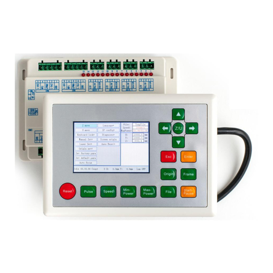
RDV6442G Control System manual V1.3 3.1 Object Pictures of MainBoard For more detailed pin description, see the Chapter 4: Description of Interface Signal for MainBoard. Figure: 3.1-1 Object Picture of MainBoard 3.2 Object Pictures of Panel Figure: 3.2-1 Object Picture of Panel... -
Page 16: Electric Connection
RDV6442G Control System manual V1.3 3.3 Electric connection ure 3.3-1 electric connection 3.4 Lamp instruction RDC6442G have fifteen red lamps: LED NUMBER NAME SENSE LED1 LmtX- negative limit indicator LED2 LmtX+ positive limit LED3 LmtY- negative limit LED4 LmtY+ positive limit... -
Page 17: Chapter 4 Description Of Interface Signal For Mainboard
RDV6442G Control System manual V1.3 Section 4 Description of Interface Signal for MainBoard CONTENTS: Interface of Main Power Source CN0 Panel Signal-Cable Interface HMI Udisk Interface PC-USB Interface Ethernet Interface General Output Port CN1 General Input Port CN2 SHENZHEN RUIDA TECHNOLOGY... - Page 18 RDV6442G Control System manual V1.3 4-axle Spacing Input Interface CN3/CN4 X/Y/Z/U axle Motor Driver Interface AXIS_X~AXIS_U Laser Power Control Interface CN5/CN6 SHENZHEN RUIDA TECHNOLOGY...
-
Page 19: Interface Of Main Power Source Cn0
RDV6442G Control System manual V1.3 4.1 Interface of Main Power Source CN0 Symbols Definitions 24V power ground (input) +24V 24V power positive (input) This control system employs single 24 power supply. For a certain margin, it is suggested to select 24V/2A power. Besides, this system is... -
Page 20: General Input Port Cn2
RDV6442G Control System manual V1.3 Power ground (output) Out2 General output, with the function reserved. Out1 General output, with the function reserved. Status General output for the signal port of running status. If this port is externally connected with the relay, the relay coil is broken over when it works;... -
Page 21: 4-Axle Spacing Input Interface Cn3/Cn4
RDV6442G Control System manual V1.3 will be restarted, that is to say, the function of the pedal switch is the same as that of the “Start/Pause” key. If the interval time to the first stepping-down of the pedal should be less than 100ms when the pedal is stepped down once again, the second stepping-down of the pedal will be considered invalid by the mainboard. -
Page 22: X/Y/Z/U Axle Motor Driver Interface Axis_X~Axis_U
RDV6442G Control System manual V1.3 motion axle leaves the spacing position, it will trigger a high-level signal or disconnect the spacing signal so as to make the spacing indicator go out, but when it leaves the spacing, the corresponding indicator will light and the spacing polarity become positive. - Page 23 RDV6442G Control System manual V1.3 low-level form, this pin will be connected with the laser power enable end and used to control the ON/Off of laser. LPWM1 Power control interface of laser/laser tube 1. When the laser is the RF laser, this pin will be connected with the laser RF-PWM end;...
-
Page 24: Chapter 5 Examples Of Laser Power Interface
RDV6442G Control System manual V1.3 Section 5 Examples of Laser Power Interface CONTENTS: Brief Examples of Glass tube Laser Power Examples of RF-Laser SHENZHEN RUIDA TECHNOLOGY... -
Page 25: Brief
RDV6442G Control System manual V1.3 5.1 Brief This control system has two independent and adjustable digital laser power control interfaces, which can be used to control glass tube laser power and RF-laser. Please correctly select the laser type in the factory parameters, or, the laser control is incorrect. -
Page 26: Examples Of Rf-Laser
RDV6442G Control System manual V1.3 5.3 Examples of RF-Laser SHENZHEN RUIDA TECHNOLOGY... -
Page 27: Chapter 6 Examples Of Driver Interface For Step-Servo Motor
RDV6442G Control System manual V1.3 Section 6 Examples of Driver Interface for Step-servo Motor CONTENTS: Brief Examples of Motor Driver Connection SHENZHEN RUIDA TECHNOLOGY... -
Page 28: Brief
RDV6442G Control System manual V1.3 6.1 Brief The input signal end of step-servo motor driver employs the light-coupled isolation technology. For the step-by-step impulse signal, some isolate the side OC diode from cutoff to conduction (e.g. the valid falling edge of pulse signal inputted from the diode minus end) and some do so from conduction to cutoff (e.g. -
Page 29: Examples Of Motor Driver Connection
RDV6442G Control System manual V1.3 6.2 Examples of Motor Driver Connection SHENZHEN RUIDA TECHNOLOGY... -
Page 30: Chapter7 Examples Of Io-Port Wiring
RDV6442G Control System manual V1.3 Section 7 Examples of IO-port Wiring CONTENTS: Input Output SHENZHEN RUIDA TECHNOLOGY... -
Page 31: Input
RDV6442G Control System manual V1.3 7.1 Input The two water protection inputs are 24V logic level; all other inputs are compatible with 5V/12V/24V logic level. Input connection shown as below Figure 7.1-1 example of input 7.2 Output All outputs are isolated through the optocoupler, and 500mA current for each, OC gate output, each can directly drive the 6V/24V relay, led lamp, buzzer etc. - Page 32 RDV6442G Control System manual V1.3 Figure 7.2-1 example of output SHENZHEN RUIDA TECHNOLOGY...
-
Page 33: Introduction To The Panel And Keys
RDV6442G Control System manual V1.3 Section 8 Examples of IO-port Wiring CONTENTS: Introduction to the Panel and Keys Introduction to the Main Interface Z/U Key File Key Introduction to some alarm info SHENZHEN RUIDA TECHNOLOGY... -
Page 34: The Whole Panel
RDV6442G Control System manual V1.3 8.1 Introduction to the Panel and Keys 8.1.1 The whole panel 8.1.2 Introduction to the Keys :Reset the whole system; :Set the relative origin; :Let the Laser to splash; :To track by the current file’s frame;... -
Page 35: Introduction To The Main Interface
RDV6442G Control System manual V1.3 :Set the speed of the current running layer, or set the direction keys’ move speed; :Set the max laser power of the current running layer, or set the power of “Laser” Key; :Set the min laser power of the current running layer;... -
Page 36: Speed Key
RDV6442G Control System manual V1.3 Figure 8.2-1 ●Graph Display Area: To display the whole file’s track, and display the running track. ●Running parameters: To display the running file’s file number, speed, max power etc.; ●Coordinate: To display the current coordinate of X,Y and Z axes ●Graph layer parameters: To display the layers’... -
Page 37: Max/Min Power Keys
RDV6442G Control System manual V1.3 Figure 8.2-2 Push the “X+/- “ Keys to move the cursor in the numeral area, and push the “Y+/-” keys to change the value, then push the “Enter” key to save the change, push the “Esc” key to invalidate the change. -
Page 38: Set The Layer Parameters
RDV6442G Control System manual V1.3 8.2.4 Set the layer parameters After selecting a file to preview on the main interface, user can push “Enter” key to let the cursor move to the first layer, then “Y+/-” Keys can be pushed to select the intent layer, on that time, user can push “Enter”... -
Page 39: Z Move
RDV6442G Control System manual V1.3 Figure 8.3-1 Push “Y+/-” keys to move the green block to the anticipant item, and then push the “Enter” key to display the sub menu. 8.3.1 Z move When the green block is on “Z Move” item, “X+/-” keys can be used to move the z axes. -
Page 40: Manual Set
RDV6442G Control System manual V1.3 Figure 8.3-2 Push the “Y+/- “ Keys to move the cursor to one of the entry, then push “Enter” key to restart the selected axis, the screen will show some information when resetting. 8.3.4 Manual set+ When the green block is on this item, push the “Enter”... -
Page 41: Laser Set
RDV6442G Control System manual V1.3 8.3.5 Laser set+ When the green block is on this item, push the “Enter” key to show as below: Figure 8.3-4 Push “Z/U” key to move the green block, and when the green block is on the “Mode” item, push “X+-“... -
Page 42: Set Fact Para
RDV6442G Control System manual V1.3 Push “Z/U” key to move the green block to the anticipant item, and when the green block is on “enable” items, push “Enter” key to enable or disable the item, when enabled, the small diamonds is green, and when disabled, the small diamonds is grey. -
Page 43: Def Fact Para
RDV6442G Control System manual V1.3 Figure 8.3-6 Push “X+/-” keys and “Y+/-” keys to select the characters, and push the “Enter” key to valid the characters, when finishing enter the password ,that is to say, the six characters, if the password is error, it prompts there is some error, or, all parameters are stored. -
Page 44: Ip Setup
RDV6442G Control System manual V1.3 Figure 8.3-7 8.3.11 IP Setup When the green block is on this item, push the “Enter” key to show as below: Figure 8.3-8 Push “Z/U” key to move the changing item, then push “X+/-” keys and “Y+/-” keys to change the value, when all the IP value and the Gateway value are changed, push “Enter”... -
Page 45: Screen Origin
RDV6442G Control System manual V1.3 Figure 8.3-9 This interface shows some system input information, such as limiter status, the status of the water protecting, and the status of the foot switch etc.. When the input is validated, the color frame will be green, otherwise it’s gray. -
Page 46: File Key
RDV6442G Control System manual V1.3 This item is only used to preview the file on the screen, and it is no meaning to the machine’s movement. Caution 8.4 File Key 8.4.1 Memory File On the main interface, if “File” key is pressed, it will show as below: Figure 8.4-1... -
Page 47: U Disk File
RDV6442G Control System manual V1.3 ●Clear count: To clear the running times of the selected file; ●Delete: To delete the selected file in the memory; ●Copy to Udisk: To copy the selected file to Udisk; If the “Other” entry is pressed, the system will show as below: Figure 8.4-2... -
Page 48: Introduction To Some Alarm Info
RDV6442G Control System manual V1.3 Figure 8.4-3 ●Read Udisk: read the file list in the Udisk; ●Copy to memory: copy the target Udisk file to the memory; ●Delete: delete the selected Udisk file; This system supports such file formats of Udisk as FAT32 and FAT16, but it can identify them when the files are put under the root directory of Udisk. -
Page 49: Chapter 9 Manufacturer/User Parameters Explanation
RDV6442G Control System manual V1.3 Section 9 Manufacturer/User Parameters Explanation CONTENTS: Manufacturer parameters User parameters SHENZHEN RUIDA TECHNOLOGY... -
Page 50: Manufacturer Parameters
RDV6442G Control System manual V1.3 9.1 Manufacturer parameters (1)Motor parameters X/Y/Z/U axle parameters Direction Polarity: Modification of direction polarity can move the motor to the opposite direction. The modification purpose can move this axle to the origin on resetting. If this axle moves far from the origin on resetting, it means the direction polarity of this axle is wrong in setting and should be modified. - Page 51 RDV6442G Control System manual V1.3 reduce the running speed of the whole figure. For the axles with larger inertia, such as Y axle corresponding to the beam, its typical setting range is 800~3000mm/s2; for the axles with smaller inertia, such as X axle corresponding to the car, its typical setting range is 8000~20000mm/s2.
-
Page 52: User Parameters
RDV6442G Control System manual V1.3 If it is only provided with the single laser, it can show the one-path parameter. Prompt (3)Other manufacturer parameters Machine configuration Machine Type: In most cases, the general engraving machine should be selected and other types used for specific purposes. - Page 53 RDV6442G Control System manual V1.3 stroke speed and idle stroke acceleration can be set higher to reduce the working time of the whole figure, but if they are set too high, it may cause the jarring of track, so comprehensive consideration should be given to the setting.
- Page 54 RDV6442G Control System manual V1.3 The cutting and scanning parameters can’t exceed the limited ones in the axle parameters. If so, the setting will become ineffective and the Prompt system will automatically cover the parameters with the axle parameters. (3)Feeding parameters ...
- Page 55 RDV6442G Control System manual V1.3 the to-and-fro cutting of array in sequence; one-way array means the cutting of array from one direction to another. On selecting one-way array, the elements of each array are the same in action mode and completely uniform in action fluency, which takes a little more time than two-way array.
- Page 56 RDV6442G Control System manual V1.3 Thank you for your selection of our production! All the copyright of this manual is owned by Ruida technology. Any person or company can not copy upload and send the manual without Ruida’s permission. Content will be revised or modified. We will not send message to every users.
Need help?
Do you have a question about the RDV6442G and is the answer not in the manual?
Questions and answers