Table of Contents
Advertisement
Laser cutting engraving control system user
RuiDa Technology Co., Ltd
Addr:
202-203,B-Block,Technology
Avenue,Nanshan
Province,P.R.China
Tel:
0755--26066687
Fax:
0755--26982287
E-mail:
sales@rd-acs.com
Web:
www.rd-acs.com
SHENZHEN RUIDA TECHNOLOGY
Read this manual before operation
The content include of electric connections and operating steps
Read the manual to operate the systems
RDC6432G
Building,NO.,1057
District,Shenzhen
city,Guangdong
RDC6432G control system user manual
Nanhai
V1.1
manual
Advertisement
Table of Contents

Related Manuals for Ruida Technology RDC6432G


Summary of Contents for Ruida Technology RDC6432G
- Page 1 V1.1 RDC6432G control system user manual Read this manual before operation The content include of electric connections and operating steps Read the manual to operate the systems RDC6432G Laser cutting engraving control system user manual RuiDa Technology Co., Ltd...
- Page 2 V1.1 RDC6432G control system user manual COPYRIGHT All rights reserved.You may not reproduce, transmit, store in a retrieval system or adapt thispublication, in any form or by any means, without the prior written permissionof RuiDa, except as allowed under applicable copyright laws.
- Page 3 V1.1 RDC6432G control system user manual CERTIFICATION DECLARATION The product has been certified by the CE (Commutate European) safety certification. It has passed the corresponding conformity assessment procedure and the manufacturer's declaration of conformity, in accordance with the relevant EU directive.
- Page 4 V1.1 RDC6432G control system user manual SAFETY INFORMATION When using this system, please make sure the operation is correct and the usage is safe. Some signs or text will be used to remind you to pay attention to the dangerous matters and some important information.
- Page 5 If any missing parts or damaged parts are found, please contact ruida technology immediately.Do not install or debug the equipment if any obvious damage is found.
-
Page 6: Table Of Contents
V1.1 RDC6432G control system user manual Contents Section 1 Overview............................1 1.1 RDC6432G Control System Introduction....................1 Section 2 Installation dimensions........................ 2 2.1 Mainboard installation size........................ 4 2.2 Panel mounting dimensions.......................5 Section 3 Physical maps and interfaces....................... 6 3.1 Picture of mainboard......................... 7 3.2 Picture of panel.......................... - Page 7 V1.1 RDC6432G control system user manual 8.5.4 Multi-point setting........................35 8.5.5 Screen origin setting......................... 36 8.5.6 Language settings........................37 8.5.7 Diagnosis........................... 37 8.5.8 System Information........................38 8.5.9 Back up factory parameters...................... 39 8.5.10 Restore factory parameters....................40 8.5.11 Controller management......................40 8.5.12 Backup to U disk........................40 8.5.13 Restore parameters from U disk.....................
-
Page 8: Section 1 Overview
V1.1 RDC6432G control system user manual Section 1 Overview CONTENTS: RDC6432G Control System Introduction SHENZHEN RUIDA TECHNOLOGY... - Page 9 RDC6432G control system user manual 1.1 RDC6432G Control System Introduction RDC6432G system is a laser engraving and cutting control system developed by Ruida Technology. The control system has better hardware stability, anti-high voltage and anti-static characteristics. The HMI system based on 3.5-inch color screen has a more friendly operation interface and more powerful functions.
-
Page 10: Section 2 Installation Dimensions
V1.1 RDC6432G control system user manual Section 2 Installation Dimensions CONTENTS: Mainboard installation size Panel mounting dimensions SHENZHEN RUIDA TECHNOLOGY... -
Page 11: Mainboard Installation Size
V1.1 RDC6432G control system user manual 2.1 Mainboard installation size All dimensions are in mm, accurate to 0.1mm (four of the positioning holes are symmetrical) SHENZHEN RUIDA TECHNOLOGY... -
Page 12: Panel Mounting Dimensions
V1.1 RDC6432G control system user manual 2.2 Panel mounting dimensions All dimensions are in mm, accurate to 0.1mm SHENZHEN RUIDA TECHNOLOGY... -
Page 13: Section3 Physical Maps And Interfaces
V1.1 RDC6432G control system user manual Section3 Physical maps and interfaces CONTENTS: Picture of mainboard Picture of Panel SHENZHEN RUIDA TECHNOLOGY... -
Page 14: Picture Of Mainboard
V1.1 RDC6432G control system user manual 3.1 Picture of mainboard For more detailed pin description, see Chapter 4 Interface Signal Description. Figure 3.1-1 Picture of Mainboard SHENZHEN RUIDA TECHNOLOGY... -
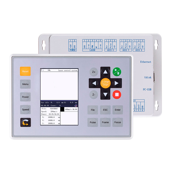
Page 15: Picture Of Panel
V1.1 RDC6432G control system user manual 3.2 Picture of panel Figure 3.2-1 Picture of Panel SHENZHEN RUIDA TECHNOLOGY... -
Page 16: Control System Electrical Connection Diagram
V1.1 RDC6432G control system user manual 3.3 Control system electrical connection diagram Figure 3.3-1 Control system electrical connection diagram SHENZHEN RUIDA TECHNOLOGY... -
Page 17: Section 4 Mainboard Interface Signal Description
V1.1 RDC6432G control system user manual Section 4 Mainboard Interface Signal Description CONTENTS: Main power connector power Mainboard and display connector HMI Udisk Interface PC-USB Interface General/dedicated OUTPUT Dedicated/ General input interface INPUT Three-axis limit input interface LIMIT X/Y/U Three-axis drive interface AXIS_X~AXIS... -
Page 18: Main Power Connector Power
V1.1 RDC6432G control system user manual 4.1 Main power connector POWER Symbols Definitions 24V power ground (input) +24V 24V power positive (input) This control system uses a single 24V power supply. In order to leave a certain margin, it is recommended to choose a power Caution supply of 24V / 2A or more. -
Page 19: General/Dedicated Output
V1.1 RDC6432G control system user manual 4.5 General/dedicated OUTPUT General and dedicated output definition Signal Definition Dedicated output. When fan control is enabled, this port outputs fan control signal, otherwise it is the first brush control signal. When the fan is connected and the fan control is enabled, Aux.Air... -
Page 20: Dedicated/ General Input Interface Input
V1.1 RDC6432G control system user manual 4.6 Dedicated/ General input interface INPUT Signal Definition +24V Power supply + 24V (output) General input, reserved General input, for a remote laser shot control. When connected to GND, it can perform laser pulse. -
Page 21: X/Y/U Three-Axis Drive Interface Axis_X~Axis_U
V1.1 RDC6432G control system user manual The limit polarity is optional. That is, if the motion axis reaches the limit position, a low voltage signal is triggered to make the LED corresponding limit lights up. And the motion axis leaves the limit position, a high voltage signal is triggered or the limit signal connection is disconnected to make When the limit indicator is off, the limit polarity is negative at this time;... -
Page 22: Laser Power Control Interface
V1.1 RDC6432G control system user manual 4.9 Laser power control interface Signal Definition Laser power ground (output) Laser enable control interface 1.When the laser is a RF laser, this pin is reserved 2. When the laser is a glass tube, if the laser power is low-voltage... -
Page 23: Section 5 Examples Of Laser Power Interface
V1.1 RDC6432G control system user manual Section 5 Examples of Laser Power Interface CONTENTS: Overview Diagram of glass tube laser power connection RF CO2 laser wiring diagram SHENZHEN RUIDA TECHNOLOGY... -
Page 24: Overview
V1.1 RDC6432G control system user manual 5.1 Overview This control system has two independent and adjustable laser power control interfaces, which can control the glass tube laser power and RF CO2 laser. When connecting different laser power types, please set the laser type correctly in the manufacturer's parameters, otherwise it may cause the laser fire to be incorrect. -
Page 25: Diagram Of Glass Tube Laser Power Connection
V1.1 RDC6432G control system user manual 5.2 Diagram of glass tube laser power connection Figure 5.2-1 Example of glass tube laser connection SHENZHEN RUIDA TECHNOLOGY... -
Page 26: Rf Co2 Laser Wiring Diagram
V1.1 RDC6432G control system user manual 5.3 RF CO2 laser wiring diagram Figure 5.3-1 Example of RF CO2 laser connection SHENZHEN RUIDA TECHNOLOGY... -
Page 27: Section 6 Example Of Stepper Motor Driver Interface
V1.1 RDC6432G control system user manual Section 6 Example of Stepper Motor Driver Interface CONTENTS: Overview Drive connection diagram SHENZHEN RUIDA TECHNOLOGY... -
Page 28: Overview
Figure 6.1-1 and Figure 6.1-2 . Each motor driver interface of RDC6432G mainrboard provides a direction signal, a pulse signal, and a 5V signal for common anode connection. The pulse signal and direction signal are both OC output. -
Page 29: Drive Connection Diagram
V1.1 RDC6432G control system user manual 6.2 Drive connection diagram Figure 6.2-1 Example of driver connection SHENZHEN RUIDA TECHNOLOGY... -
Page 30: Section 7 Io Port Wiring Example
V1.1 RDC6432G control system user manual Section 7 IO Port Wiring Example CONTENTS: Input port Output port SHENZHEN RUIDA TECHNOLOGY... -
Page 31: Input Port
V1.1 RDC6432G control system user manual 7.1 Input port The water protection input port WP of this controller is only compatible with 24V. All other input ports are compatible with input 5V / 12V / 24V. The wiring diagram of the input port is as follows: Figure 7.1-1 Example of input... -
Page 32: Output Port
V1.1 RDC6432G control system user manual 7.2 Output port All output signals of this controller are output based on opto-coupler isolation technology and OC gate output. Its maximum driving capacity is 300mA, which can directly drive 6V / 24V relays, light-emitting indicators, buzzer alarm devices, etc. -
Page 33: Section 8 Hmi Operation Instructions
V1.1 RDC6432G control system user manual Section 8 HMI operation instructions CONTENTS: HMI introduction Speed Setting Power setting Layer function Menu Function File management Password input and setting Prompt and alarm information Parameter setting operation SHENZHEN RUIDA TECHNOLOGY... -
Page 34: Hmi Introduction
RDC6432G control system user manual 8.1 HMI introduction RDC6432G-HMI panel (hereinafter referred to as "panel") is a HMI based on 3.5TFT LCD screen, with beautiful interface, friendly, smooth control, high cost performance. The panel can depict the motion track of the controller in real time, allowing users to see the current processing graphics clearly, support file management, file preview, parameter modification, support multi-language interface switching and other functions. -
Page 35: Key Function Description
V1.1 RDC6432G control system user manual 8.1.2 Key function description “RESET”:Reset system “RUN/PAUSE”:Start job or pause / restart job “PULSE”:Laser tube pulse(Note: Press ‘Shift ’+‘Pulse’ for continuous pulse) “STOP”:Stop processing/Motor axis movement “FOCUS”:Auto Focus “MANU”: User parameters, manufacturer parameters, language ... -
Page 36: Main Interface Function
V1.1 RDC6432G control system user manual Z axis: used to move the Z axis (Note: press and hold ‘Shift’ + ‘Z+’ to return to the Z axis focus point) Speed : used to set the speed Shift Shift : use the switching function with other keys ... -
Page 37: Speed Setting
V1.1 RDC6432G control system user manual Layer parameter area:Display the layer parameters of the current processing file or the layer parameters of the preview file. The parameters from left to right are: layer color, layer speed, and layer maximum power. -
Page 38: Power Setting
V1.1 RDC6432G control system user manual 3. After setting, press [Enter] to save the modified parameters, and press [ESC] to exit the interface. 8.3 Power Setting Press [Power] key in the main interface, the following interface will pop up: Figure 8.3-1 1. -
Page 39: Menu Function
V1.1 RDC6432G control system user manual area. At this time, the "red selection box" appears in the first line of the layer list, as shown in the figure below: Figure 8.4-2 User can press the up and down keys to select the layer number, and the "select block" will also move. -
Page 40: Jog Settings
V1.1 RDC6432G control system user manual Figure 8.5-1 Press the panel direction keys to select the parameter to be set, the selected parameter box will change from black to red. Press [Enter] key to enter the Submenu, and press [ESC] key to return to the previous menu. -
Page 41: Pulse Setting
V1.1 RDC6432G control system user manual 8.5.2 Pulse setting When the "red selection box" stops on the item and press the [Enter] key, the following interface will pop Figure 8.5.2-1 Please refer to section 8.5.1 for setting steps. If the pulse mode is selected as "continuous", the laser will always on when the pulse button is pressed, and the laser will be turned off when the start button is ejected. -
Page 42: Multi-Point Setting
V1.1 RDC6432G control system user manual Figure 8.5.3-2 8.5.4 Multi-point setting In the menu interface, select the “positioning Settings" item, press [Enter] key and then the following interface will pop up: Figure 8.5.4-1 At this time, the "red selection box" defaults to the "multi point enable" item, press the [Enter] key to... -
Page 43: Screen Origin Setting
V1.1 RDC6432G control system user manual Figure 8.5.4-2 Press the up, down, left, and right keys to move the X or Y axis to the target position. After pressing the [Origin] key, the original coordinates will become the current coordinates. Press [ESC] to exit the interface and the parameters will take effect automatically, and then press the [ESC] key to return to the previous menu. -
Page 44: Language Settings
V1.1 RDC6432G control system user manual Figure 8.5.5-1 Set the origin position of the display screen here, and select different screen origin positions to mirror the displayed graphics in different X/Y directions. Press the arrow keys to select a position and then press the [Enter] key, the screen origin position will be displayed as the currently selected position, press [ESC] to return to the main menu interface. -
Page 45: System Information
V1.1 RDC6432G control system user manual Figure 8.5.7-1 This interface displays the hardware IO port information of the system: trigger Not triggered Input signal: Read system hardware information. When the hardware signal is triggered, the small box on the left of the corresponding item will be red, otherwise it will be gray. -
Page 46: Back Up Factory Parameters
V1.1 RDC6432G control system user manual 2. When all the passwords are entered and correct, it will prompt again: press < Enter > to confirm the password. (Password length is 6 English letters or numbers) 3. Press【Enter】key to enter the following interface: Figure 8.5.8-2... -
Page 47: Restore Factory Parameters
V1.1 RDC6432G control system user manual 8.5.10 Restore factory parameters In the menu interface, select the "Restore default”, and press the [ENT] key to pop up the password input interface, fill in “HF8888”. If the password is entered correctly, the system will restore all current user parameters and vendor parameters with the factory parameters that were set before. -
Page 48: Restore Parameters From U Disk
V1.1 RDC6432G control system user manual Figure 8.5.11-2 If there is a problem with the U disk, it will prompt "Parameter backup failed". Figure 8.5.11-3 8.5.13 Restore parameters from U disk When the "red selection box" stops on the item, press [Enter] and enter the password. Please refer to section 8.5.8 for the password input operation, the following interface will pop up:... -
Page 49: Time Setting
V1.1 RDC6432G control system user manual Figure 8.5.11-5 8.5.14 Time setting When the "red selection box" stops on the item and press the [Enter] key, the following interface will pop Figure 8.5.11-6 This interface can only be displayed when the system is not encrypted. The parameter setting steps are as follows: 1. -
Page 50: Permission Management
V1.1 RDC6432G control system user manual to modify. 5. After all modifications are completed. Select the item [write], press [Enter] to save the parameter settings, and press [ESC] to return to the previous menu interface. 8.5.15 Permission Management The product should be authorized if users are the first time to choose RUIDA If the current product is not authorized, choose the option of “Permission”, press [ENT] and the following... -
Page 51: Ip Setting
V1.1 RDC6432G control system user manual Figure 8.5.12-3 4. Use the "up, down, left, and right" direction keys to select the corresponding character, and press [Enter] to confirm the input. If you make a mistake in the operation, just press [Exit] to reselect and press [Enter] to enter the setting. -
Page 52: Z-Axis Stop Setting
V1.1 RDC6432G control system user manual Figure 8.5.13-1 2. Use the arrow keys to select the item to be set, the red box is the selected item, as shown in the figure below, press [Enter]: Figure 8.5.13-2 3. After pressing the [Enter] key, an underline will be added to the number of the item. Users can use the... - Page 53 V1.1 RDC6432G control system user manual Figure 8.5.14-1 There are two ways to set the Z-axis point, one is to directly input the Z-axis coordinate, and the other is to set the current coordinate position. Enter the Z coordinate 1. As shown in the figure below, select the input box with the arrow keys , and press [Enter] to enter the editing state.
-
Page 54: File Management
V1.1 RDC6432G control system user manual Figure 8.5.14-2 2. Press [Enter] on the panel to save the settings. 3. Press【ESC】key to return to the main menu interface. Note: Before getting the current position, users can move the Z axis to the desired position, and then enter this menu to set the Z axis origin point. - Page 55 V1.1 RDC6432G control system user manual stops on the item, press the up and down keys to select the item and press [ENT] to select the item. Press [Esc] to return to the main interface. The contents of the entries on the right and bottom are as follows: Work time check: The total processing time of the file is predicted, and the difference between the ...
-
Page 56: Array Information
V1.1 RDC6432G control system user manual 8.6.2 Array information 1. In the above interface, select the "Array Information" item and press [Enter] key, then the pop-up menu is shown in the following figure: Figure 8.6.2-1 2. Then in the above interface, press... -
Page 57: Feeding Parameters
V1.1 RDC6432G control system user manual 7. After the parameters are set, select [Write Parameters], and press [Enter] to save the parameter settings. 8.6.3 Feeding parameters In the above interface, select the "Feeding Parameters" item and press [Enter] key, then the pop-up menu is shown as below: Figure 8.6.3... -
Page 58: Format Memory
V1.1 RDC6432G control system user manual Current work time: Preview the processing time of the currently selected file. Clear all files: Clear the number of processed files in flash memory. Del all memory files: delete all memory files. -
Page 59: Password Input And Setting
V1.1 RDC6432G control system user manual The operation method is the same as the memory file, press [ESC] key to return to the "File" interface. Read U disk file: read the U disk file list. Copy to memory: copy the selected file to internal memory. -
Page 60: Parameter Setting Operation
V1.1 RDC6432G control system user manual The system pops up and the system is resetting, the interface is as follows: Figure 8.8-1 Operate according to the interface prompts. Alarm information The system pops up a water protection failure, the interface is as follows: Figure 8.8-2... -
Page 61: Number Parameter
V1.1 RDC6432G control system user manual 4. After setting all the parameters, select [write parameters] and press [Enter] 8.9.2 Number parameter When user modify the numerical parameters, select the parameter box and press the [OK] key, the cursor appears below the first digit ( ),At this time, press the "up and down"... - Page 62 V1.1 RDC6432G control system user manual the underlined value. :Select the parameter box and move the number underline 【ESC】Cancel, return to the previous level [Enter] Confirm, save, and enter the next leve SHENZHEN RUIDA TECHNOLOGY...
- Page 63 RDC6432G control system user manual Thank you for your selection of our production! All the copyright of this manual is owned by Ruida technology. Any person or company can not copy upload and send the manual without Ruida’s permission. Content will be revised or modified. We will not send message to every users.
Need help?
Do you have a question about the RDC6432G and is the answer not in the manual?
Questions and answers