Table of Contents
Advertisement
Quick Links
RuiDa Technology Co., Ltd
Add: Unit 202,Block B, Technology Building, NO., 1067 Nanhai
Avenue, Nanshan District, Shenzhen city, Guangdong
Province, P.R.China P.C:518054
Tel:
0755--26066687
Fax:
0755--26982287
E-mail:
sales@rd-acs.com
Web:
www.rd-acs.com
SHENZHEN RUIDA TECHNOLOGY
Read this manual before operation
The content include of electric connections and operating steps
Read the manual to operate the systems
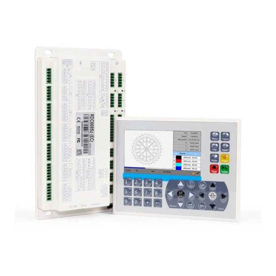
RDC6685U(-DFM)
RDC6685U(-DFM) Control System manual
Control System manual
https://www.ruidacontroller.com
Advertisement
Table of Contents

Related Manuals for Ruida Technology RDC6685U


Summary of Contents for Ruida Technology RDC6685U
- Page 1 RDC6685U(-DFM) Control System manual Read this manual before operation The content include of electric connections and operating steps Read the manual to operate the systems RDC6685U(-DFM) Control System manual RuiDa Technology Co., Ltd Add: Unit 202,Block B, Technology Building, NO., 1067 Nanhai Avenue, Nanshan District, Shenzhen city, Guangdong Province, P.R.China P.C:518054...
- Page 2 RDC6685U(-DFM) Control System manual COPYRIGHT All rights reserved.You may not reproduce, transmit, store in a retrieval system or adapt thispublication, in any form or by any means, without the prior written permissionof RuiDa, except as allowed under applicable copyright laws. We have identifiedwords that we consider as trademarks.
- Page 3 RDC6685U(-DFM) Control System manual CERTIFICATION DECLARATION The product has been certified by the CE (Commutate European) safety certification. It has passed the corresponding conformity assessment procedure and the manufacturer's declaration of conformity, in accordance with the relevant EU directive. ROHS This product has been certified by EU legislation (Restriction of Hazardous Substances) Safety certification;...
- Page 4 RDC6685U(-DFM) Control System manual SAFETY INFORMATION When using this system, please make sure the operation is correct and the usage is safe. Some signs or text will be used to remind you to pay attention to the dangerous matters and some important information.
- Page 5 If any missing parts or damaged parts are found, please contact ruida technology immediately.Do not install or debug the equipment if any obvious damage is found.
-
Page 6: Table Of Contents
RDC6685U(-DFM) Control System manual Contents Section 1 Overview............................. 3 1.1 B ..............................4 RIEFING 1.2 D ....................4 ESCRIPTION OF ONTROLLER ODEL 1.3 L ......................5 IST OF ONTROLLER UNCTIONS Section 2 Installation Size.......................... 7 2.1 I ...................... 8 NSTALLATION IZE OF OARD 2.2 S... - Page 7 RDC6685U(-DFM) Control System manual 8.5 M ........................... 38 UNCTION 8.5.1 User parameters..........................38 8.5.2 Vender parameters..........................41 8.5.3 Origin Setting..........................42 8.5.4 Backup parameters.........................44 8.5.5 Restore parameters.........................44 8.5.6 Max/Min Power Setting......................... 44 8.5.7 Permission Settings........................45 8.6 C ........................... 46 ONTROLLER SETTING 8.6.1 Language............................
-
Page 8: Section 1 Overview
RDC6685U(-DFM) Control System manual Section 1 Overview CONTENTS: Briefing Description of Controller Model List of controller functions SHENZHEN RUIDA TECHNOLOGY... -
Page 9: Briefing
RDC6685U(-DFM) Control System manual 1.1 Briefing RDC6685U(-DFM) system is the latest generation of dual X / Y coordinate system controller developed by Ruida technology. The control system has better hardware stability and better anti-voltage and anti-static interference characteristics. The HMI based on 5-inch color screen has more friendly operation interface and more powerful functions. -
Page 10: List Of Controller Functions
RDC6685U(-DFM) Control System manual 1.3 List of Controller Functions RDC6685U(-DFM) Power Feature Only one-way 24V (3A and above drive capability) Laser Port Feature 4-way laser port, digital and analog supported Copying Speed USB Feature Very Quick Compatibility Support all USB disks with different capacities... - Page 11 RDC6685U(-DFM) Control System manual Feature hardware encryption Communicate 10/100MHZ Ethernet or USB2.0, communication mode is Mode automatically checked SHENZHEN RUIDA TECHNOLOGY...
-
Page 12: Section 2 Installation Size
RDC6685U(-DFM) Control System manual Section 2 Installation Size CONTENTS: Installation Size of MainBoard Size of Panel SHENZHEN RUIDA TECHNOLOGY... -
Page 13: Installation Size Of Mainboard
RDC6685U(-DFM) Control System manual 2.1 Installation Size of MainBoard The unit of all sizes is millimeter (mm) and the size accurate to 0.1mm (the four holes are symmetrical) 2.2 Size of Panel The unit of all sizes is millimeter (mm) and the size accurate to 0.1mm. - Page 14 RDC6685U(-DFM) Control System manual SHENZHEN RUIDA TECHNOLOGY...
-
Page 15: Section 3 Object Pictures And Interfaces
RDC6685U(-DFM) Control System manual Section 3 Object Pictures and Interfaces CONTENTS: Object Pictures of MainBoard Object Pictures of Panel Electric connection Lamp instruction Interpretation of dual Y /dual X coordinate SHENZHEN RUIDA TECHNOLOGY... - Page 16 RDC6685U(-DFM) Control System manual SHENZHEN RUIDA TECHNOLOGY...
-
Page 17: Object Pictures Of Mainboard
RDC6685U(-DFM) Control System manual 3.1 Object Pictures of MainBoard For more detailed pin description, see the Chapter 4: Description of Interface Signal for MainBoard. Figure: 3.1-1 Object Picture of MainBoard SHENZHEN RUIDA TECHNOLOGY... -
Page 18: Object Pictures Of Panel
RDC6685U(-DFM) Control System manual 3.2 Object Pictures of Panel Figure: 3.2-1 Object Picture of Panel SHENZHEN RUIDA TECHNOLOGY... -
Page 19: Electric Connection
RDC6685U(-DFM) Control System manual 3.3 Electric connection Figure 3.3-1 electric connection SHENZHEN RUIDA TECHNOLOGY... -
Page 20: Lamp Instruction
RDC6685U(-DFM) Control System manual 3.4 Lamp instruction RDC6685U(-DFM) have 22 red lamps: NUMBER NAME SENSE LmtX1- X1 axis negative limit LmtY1- Y1 axis negative limit LmtZ1- Z1 axis negative limit LmtU1- U1 axis negative limit LmtX2- X2 axis negative limit... -
Page 21: Interpretation Of Dual Y/ Dual Xcoordinate
RDC6685U(-DFM) Control System manual 3.5 Interpretation of dual Y/dual X coordinate The system can choose double beam or double cantilever, which is to say dual Y or dual X. For each model, the coordinate system is fixed. The coordinate system X1/Y1 is the main coordinate system, and the coordinate system X2/Y2 is the secondary coordinate system. -
Page 22: Section 4 Description Of Interface Signal For Mainboard
RDC6685U(-DFM) Control System manual Section 4 Description of Interface Signal for MainBoard CONTENTS: Interface of Main Power Source CN0 Panel Signal-Cable Interface HMI Udisk Interface PC-USB Interface Ethernet Interface Extended Com port CN1 General Input Port General Output Port 8-axle Spacing Input Interface... - Page 23 RDC6685U(-DFM) Control System manual SHENZHEN RUIDA TECHNOLOGY...
-
Page 24: Interface Of Main Power Source Cn0
RDC6685U(-DFM) Control System manual 4.1 Interface of Main Power Source CN0 Symbols Definitions 24V power ground (input) +24V 24V power positive (input) The control system uses a single 24 V power supply, in order to leave a certain margin, it is recommended to choose the 24V power supply Caution above 3A. -
Page 25: General Input
RDC6685U(-DFM) Control System manual The RX for the first RS232 port The TX for the second RS232 port The RX for the second RS232 port Power ground (output) 4.7 General Input (一) Definition of CN2 Symbols Definitions FootSW Input port of foot switch. The connection method is: when the pedal is stepped down, the low-level signal will be inputted to this port;... -
Page 26: General Output
RDC6685U(-DFM) Control System manual Symbols Definitions Reserved input5 Reserved input6 Reserved input7 Reserved input8 +24V 24V Power positive (output) (三)Definition of CN5 Symbols Definitions Power ground (output) Reserved input9 In10 Reserved input10 In11 Reserved input11 In12 Reserved input12 In13 Reserved input13... -
Page 27: 8-Axle Spacing Input Interface
RDC6685U(-DFM) Control System manual Out7 Reserved Output Out8 Reserved Output Out9 Reserved Output Out10 Reserved Output Out11 Wind for X1Y1 Out12 Pen1 Out13 Pen2 +24V 24V Power positive (output) (三)Definition of CN6 Symbols Definitions Power ground (output) Wind for X2Y2... -
Page 28: 8-Axle Motor Driver Interface
RDC6685U(-DFM) Control System manual LmtX1+ The spacing from axle X1+ and X1 to max. coordinate 5V Power positive (output) The spacing polarity is optional, that is to say, when the motion axle reaches the spacing position, it will trigger a low-level signal so as to make the corresponding LED (under the cover) light;... - Page 29 RDC6685U(-DFM) Control System manual it will move to the opposite direction of machine origin, which means the polarity of directional signal for this axle is not correct. In such a case, the connection between this axle and the motor driver can be broken first (otherwise the mainboard can not be detected to the spacing so as to lead to the collision of this axle), and then such a polarity can be corrected after this axle is reset completely.
- Page 30 RDC6685U(-DFM) Control System manual forcibly close the laser to suspend the work in progress and the system will warn. If the water protector 1 is not enabled, the mainboard will not detect the input port of water protector 1 and so the water protector 1 can be unconnected.
-
Page 31: Section 5 Examples Of Laser Power Interface
RDC6685U(-DFM) Control System manual Section 5 Examples of Laser Power Interface CONTENTS: Brief Examples of Glass Tube Laser Power Examples of RF-Laser SHENZHEN RUIDA TECHNOLOGY... -
Page 32: Brief
RDC6685U(-DFM) Control System manual 5.1 Brief This control system has two independent and adjustable digital laser power control interfaces, which can be used to control glass tube laser power and RF-laser. Please correctly select the laser type in the factory parameters, or, the laser control is incorrect. -
Page 33: Examples Of Glass Tube Laser Power
RDC6685U(-DFM) Control System manual 5.2 Examples of Glass tube Laser Power SHENZHEN RUIDA TECHNOLOGY... -
Page 34: Examples Of Rf-Laser
RDC6685U(-DFM) Control System manual 5.3 Examples of RF-Laser SHENZHEN RUIDA TECHNOLOGY... -
Page 35: Section 6 Examples Of Driver Interface For Step-Servo Motor
RDC6685U(-DFM) Control System manual Section 6 Examples of Driver Interface for Step-servo Motor CONTENTS: Brief Examples of Motor Driver Connection SHENZHEN RUIDA TECHNOLOGY... -
Page 36: Brief
5V positive output, the direction signal and the pulse signal are all OC output. RDC6685U(-DFM) controller must be common anode with the motor driver. The polarity of the direction signal can be changed in the factory parameters, and the valid edge of the pulse signal can also be changed. -
Page 37: Examples Of Motor Driver Connection
RDC6685U(-DFM) Control System manual 6.2 Examples of Motor Driver Connection SHENZHEN RUIDA TECHNOLOGY... -
Page 38: Section 7 Examples Of Io-Port Wiring
RDC6685U(-DFM) Control System manual Section 7 Examples of IO-port Wiring CONTENTS: Input and Output Connecting SHENZHEN RUIDA TECHNOLOGY... -
Page 39: Input And Output Port Wiring Example
RDC6685U(-DFM) Control System manual 7.1 Input and output port wiring example ◆The 4 water protection inputs are 24V logic level; all other inputs are compatible with 5V/12V/24V logic level. ◆ All the output signals of the controller adopt optocoupler isolation technology, OC gate output, and its maximum driving capacity is 300mA, which can directly drive 5V/24V relay, luminous indicator, buzzer alarm equipment, etc. - Page 40 RDC6685U(-DFM) Control System manual SHENZHEN RUIDA TECHNOLOGY...
-
Page 41: Section 8 Operating Instruction Of Panel
RDC6685U(-DFM) Control System manual Section 8 Operating Instruction of Panel CONTENTS: Brief The main interface Speed Setting Set the layer parameters Menu Key Controller setting Functions File Management Password input and Settings Prompt and alarm Information SHENZHEN RUIDA TECHNOLOGY... -
Page 42: Brief
8.1 Brief 8.1.1 Overview RDC6685U-HMI control panel (hereinafter referred to as "panel") is a 5.0 inch TFT LCD screen based human-machine interface, with beautiful interface, man-machine friendly, smooth control, cost-effective features. The panel can depict the motion track of the controller in real time, which makes the user... -
Page 43: Introduction To The Keys
RDC6685U(-DFM) Control System manual 8.1.2 Introduction to the Keys Reset the whole system. To start or pause the work. Let the Laser to splash. Stop working or motor axis motion. User parameters, factory parameters, language settings, etc. -
Page 44: The Main Interface
RDC6685U(-DFM) Control System manual Tomove the X2 axes and Y2 Moving U1 axis. Point movement and continuous motion switching. Decimal point. Backspace. Digital key 0~9:Used to set parameters. Note: The numeric keys (1, 5) (2, 6) (3, 7) reuse the Z1, Z2, U2 axis movement functions, respectively. -
Page 45: Speed Setting
RDC6685U(-DFM) Control System manual Graph layer parameters: To display the layers’ information of the current file, such as max or min power, speed etc.. When system is idle, dblclick the layer, then users can change the layer’s parameters and the changing would be saved. -
Page 46: Set The Layer Parameters
RDC6685U(-DFM) Control System manual 8.4 Set the layer parameters After selecting a file to preview on the main interface, If there is layer information in the layer parameter area, show as below: Figure 8.4-1 User can push <Enter> key to let the cursor move to the first layer show as below: Figure 8.4-2... -
Page 47: Menu Function
RDC6685U(-DFM) Control System manual the <Esc> key interface to disappear and return to the main interface. 8.5 Menu Function Push the < Menu> key when the screen is on the main interface, it will show as below: Figure Press the <Esc> key to return to the previous menu. - Page 48 RDC6685U(-DFM) Control System manual parameters are read out, the user can press the "up/down" key to move the "blue selection block" to select a parameter category such as "carving", "feeding" and so on. The right parameter area displays the corresponding parameters. If the user does not need to modify the parameters, press the <Esc>...
- Page 49 RDC6685U(-DFM) Control System manual Figure Figure 8.5.1-3 8.5.1-4 Figure Figure 8.5.1-5 8.5.1-6 Figure Figure 8.5.1-7 8.5.1-8 Figure Figure 8.5.1-9 8.5.1-10 SHENZHEN RUIDA TECHNOLOGY...
-
Page 50: Vender Parameters
RDC6685U(-DFM) Control System manual Figure 8.5.1-11 8.5.2 Vender parameters In the menu interface, select "Vender parameters" entry and press the <Enter> key ,it will show as below: Figure 8.5.2-1 The interface parameters of X2,Y1,Y2,Z1,Z2,U1 and U2 axes are the same as those of X1 axis parameters. -
Page 51: Origin Setting
RDC6685U(-DFM) Control System manual Figure Figure 8.5.2-4 8.5.2-4 The operation and settings of the factory parameters are the same as the user parameters. 8.5.3 Origin Setting In the menu interface, select "Origin setting" entry and press the <Enter> key ,it will show as... - Page 52 RDC6685U(-DFM) Control System manual Figure Other origins are set in the same way. 8.5.3-2 When the "Select Block" stops on the "Start origin" entry, press the <Enter> key to enter the modification, press the "Up/Down" key to modify, after the modification, press the <Enter> key, the parameters automatically take effect, and press the <Esc>...
-
Page 53: Backup Parameters
RDC6685U(-DFM) Control System manual 8.5.4 Backup parameters In the menu interface, select the "Backup Factory Parameters" entry, press the <Enter> button and then pop up the password input interface. The password input operation refers to Section 8.9. If the password is input correctly, the system will backup all the current user parameters and factory parameters. -
Page 54: Permission Settings
RDC6685U(-DFM) Control System manual At this point, the "blue selection block" stays on the first parameter to indicate that the parameter is selected, press the number key and the backspace key to set and modify the parameter. Press the arrow button to move the "select block" to select other parameters for modification. -
Page 55: Controller Setting
RDC6685U(-DFM) Control System manual and press the arrow keys to select other parameter boxes, the parameter setting operation is the same as above. After all the parameters are set, move the red selection box to change the authorization code and press [OK] to set successfully. Press Exit to return to the upper operation interface. -
Page 56: Screen Origin
RDC6685U(-DFM) Control System manual Press the direction key to select a language and press the <Enter> key to set up the function and automatically return to the menu interface. 8.6.2 Screen origin Select the "Screen origin" entry under the controller setting interface, press the <Enter> button,... -
Page 57: Ip Setting
RDC6685U(-DFM) Control System manual Figure 8.6.3 When modifying the first parameter, press the <Enter> key to enter the modification mode ("blue selection block" right side becomes ), press the "Up/Down" key to modify, and then press the <Enter> key to exit the modification mode. Press the direction key to select other parameters and press the number key to modify the parameters. -
Page 58: System Info
RDC6685U(-DFM) Control System manual 8.6.5 System Info Select the "System Info" entry under the controller setting interface, press the <Enter> button, and then pop up the interface as follows: Figure 8.6.5 Press the <Enter> key to read motherboard information.Press the <Esc> key to return to the previous menu. -
Page 59: Funtions
RDC6685U(-DFM) Control System manual 8.7 Funtions In the menu interface, select "Function" entry and press the <Enter> key ,it will show as below: Figure Press the <Esc> key to return to the previous menu. 8.7.1 Axis reset Select the "Axis reset" entry under the controller setting interface, press the <Enter> button,... -
Page 60: Keyboard Lock
RDC6685U(-DFM) Control System manual 8.7.2 Keyboard lock Select the "Keyboard lock" entry under the controller setting interface, press the <Enter> button, and then pop up the interface as follows: Figure 8.7.2 Password setting This entry allows you to set the default password for keyboard locking and use the new password for keyboard locking after setting up successfully. -
Page 61: Laser Setting
RDC6685U(-DFM) Control System manual Figure 8.7.3 Manual mode has “Continue” and “Manual”, press the <Enter> key to enter the modification mode ("blue selection block" right side becomes ), press the "up/down" key to modify, after the modification, press the <Enter> key to exit the modification mode. After all modifications, move the “Select block”... -
Page 62: Diagnose
RDC6685U(-DFM) Control System manual The operation method is the same as manual setting. When “Continue” item is selected, then the “Laser time” item is not valid, on that time, push the Laser key to splash the enabled lasers, and when Laser key is loosed, then the lasers will finish splashing. -
Page 63: File Management
RDC6685U(-DFM) Control System manual Figure 8.7.6-1 When the "blue selection block" stops at the items 1, 2, 3 and 4 of the laser power supply, press the <Enter> key to view the information of each power supply. The interface is as follows: Figure 8.7.6-2... - Page 64 RDC6685U(-DFM) Control System manual Figure 8.8.1 When showing this menu, the system would read the memory file firstly, the file name and the work times would be listed in the area, and the selected file is previewed in the bottom right area.
-
Page 65: Memory Operation
RDC6685U(-DFM) Control System manual 8.8.2 Memory operation Select the "Memory Operation" entry in the above interface and press the <Enter> button, then the pop-up menu appears as follows: Figure 8.8.2 Clear all count: To clear the running times of every file in the memory ... -
Page 66: U Disk File
RDC6685U(-DFM) Control System manual Figure 8.8.3 Format speedily: To format memory speedily, and then all the files in memory will be deleted. Format drastically: To format memory drastically, and then all the files in memory will be deleted. -
Page 67: Password Input And Settings
RDC6685U(-DFM) Control System manual This system supports such file formats of Udisk as FAT32 and FAT16, but it can identify them when the files are put under the root directory of Udisk. The file name of more than 8 characters will automatically be cut Prompt out by the system. -
Page 68: Prompt And Alarm Information
RDC6685U(-DFM) Control System manual Figure 8.9.2 At this point, you can enter the password directly by pressing the number key, or you can press the <Shift> key to use the keypad, press the direction key to select a number or letter, press the <Enter>... - Page 69 RDC6685U(-DFM) Control System manual Figure 8.10-2 At this point, the system performs related operations according to the <Enter> or <Esc> keys. SHENZHEN RUIDA TECHNOLOGY...
- Page 70 RDC6685U(-DFM) Control System manual Section 9 Manufacturer/User Parameters Explanation CONTENTS: Manufacturer parameters User parameters SHENZHEN RUIDA TECHNOLOGY...
-
Page 71: Manufacturer Parameters
RDC6685U(-DFM) Control System manual 9.1 Manufacturer parameters (1)Motor parameters There are eight motion axes in the system, which are X1/Y1/Z1/U1 and X2/Y2/Z2/U2. The parameters of each axis are the same, and the meaning of the parameters is as follows: Direction Polarity: Modification of direction polarity can move the motor to the opposite direction. - Page 72 RDC6685U(-DFM) Control System manual condition. If this value is excessively large, it will make the motor lose steps, jar and even squeak; if small, it will reduce the running speed of the whole figure. If the inertia of the motion axle is larger (the axle is heavier), you can set a smaller takeoff speed;...
- Page 73 RDC6685U(-DFM) Control System manual Laser Enable: When double lasers are used, then each laser can be respectively enabled or disabled. Minimum Power Maximum Power Laser PWM Frequency Pre-generation Frequency Pre-generation pulse scale: When the laser is RF-laser and it’s need to pre-generate PWM, then set the Pre-generation Frequency and the Pre-generation pulse scale.
- Page 74 RDC6685U(-DFM) Control System manual during this time. The delay value set here should basically consistent with the actual off-delay value. If the deviation of set value is larger, on the de-energizing for continuous engraving, either the figure processed for the second time is not closed with that before the cutoff, or it is coincided with that too much.
-
Page 75: User Parameters
RDC6685U(-DFM) Control System manual 9.2 User parameters (1)Cutting parameters(Only affect cutting arts) The controller has two coordinate systems. The cutting process parameters of each coordinate system can be set separately, and the parameters are exactly the same. Their meanings are as follows: ... - Page 76 RDC6685U(-DFM) Control System manual After-feeding Time Lag: settable at 0~9.9s. It can facilitate the feeding device’s delaying in jarring after moving to the correct position and waiting for the 2 work after the feeding axle stands still completely. Last feeding: If feeding when the last times work end.
- Page 77 RDC6685U(-DFM) Control System manual Back Position X1Y1/X2Y2: The origin (the relative origin) and the machine’s absolute origin can be selected. This parameter decides the parking position of X1Y1 or X2Y2’s laser head after each work. Backlash X1/X2: The X1 or X2 axes’ backlash, accurate to 1um.
- Page 78 RDC6685U(-DFM) Control System manual Thank you for your selection of our production! All the copyright of this manual is owned by Ruida technology. Any person or company can not copy upload and send the manual without Ruida’s permission. Content will be revised or modified. We will not send message to every users.
Need help?
Do you have a question about the RDC6685U and is the answer not in the manual?
Questions and answers