Table of Contents
Advertisement
Quick Links
HydroTap G4 Tap Installation
Section 1.0
For new installations, It is recommended to fit the tap prior to installing the undersink unit.
Note: This book must be read in conjunction with the undersink installation manual and the user manual
Hole positioning:
Position the tap such that it dispenses into the sink bowl with ample clearance for a cup or tea pot.
Alternatively, the tap could be mounted away from the sink using a font, available as an accessory.
Elite
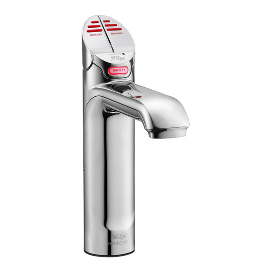
HydroTap Classic
HydroTap Arc/Cube
All-In-One
Celsius Arc/Cube
Mixer - Arc neck
Mixer - Classic
Mixer - Cube neck
** Check bowl depth and adjust accordingly
For
A-I-O 50mm and
Mixer taps 35mm
hole
For
Elite,Classic
and Arc/Cube
35mm hole
803341NZ - Tap Installation Instructions - Jun 2016 - v2.00
- Tap installation
TAP
Recommended dispensing distance **
Double Bowl
Single
Bowl
116 mm
116 mm
171 - 174 mm (Extended)
211 mm
220 mm
220 mm
270 mm
220 mm
BC HydroTap Classic
116
Page 1 of 16
Advertisement
Table of Contents

Related Manuals for Zip HydroTap G4 Tap


Summary of Contents for Zip HydroTap G4 Tap
- Page 1 HydroTap G4 Tap Installation Section 1.0 - Tap installation For new installations, It is recommended to fit the tap prior to installing the undersink unit. Note: This book must be read in conjunction with the undersink installation manual and the user manual Hole positioning: Position the tap such that it dispenses into the sink bowl with ample clearance for a cup or tea pot.
- Page 2 HydroTap Classic & Elite EliteTap HydroTap Classic ALL THREAD STAINLESS STEEL BLACK PLASTIC SPACER SPACER SPIDER CLAMP 470mm Tap assembly exploded view and kitchen layout side view. BENCH TOP Apply a light smearing of silicon sealant on the Ø35mm underside of the spacer to ensure a watertight fit. Cut a 35mm hole in the bench / sink top.
- Page 3 Installation Instructions BLACK PLASTIC STAINLESS SPACER STEEL WASHER Fit the STAINLESS STEEL WASHER, SPIDER CLAMP SPIDER CLAMP, AND 6mm NUT. 6mm NUT 35mm hole Note: feed each of the three tubes and Note electrical cable evenly in between the legs of Pass all the hoses, tubes and USB lead the SPIDER CLAMP when installing.
- Page 4 HydroTap Arc/Cube The HydroTap Arc/Cube has a spout that may be fixed in one of 6 angular positions (depending on the position of the rotary control) and fixed in one of two height positions. The spout is fixed and does not swivel. NOTE: The tube kit must be fitted after the HydroTap has been mounted on the benchtop or sink.
- Page 5 Installation Instructions Height adjustment (Fixed position options) 50mm Angular adjustment (Fixed position options) Left Hand Control Right Hand Control NOTE: Position A is not recommended with Boiling water units Mounting (See table on Page 11 ) O-RING BENCH TOP LOWER Ø35mm RUBBER WASHER...
-
Page 6: Mixer Tap Installation
Mixer Tap Installation BRAIDED HOSE x 3 Tap assembly exploded view and kitchen layout side view. 1.11 O-RING 1.10 SINK TOP LOWER RUBBER 35mm WASHER WASHER Cut a 35mm hole in the bench / sink top. Note: make sure the tap location will allow the nozzle to drain into the sink. - Page 7 Installation Instructions 1.12 (Classic, Arc and Cube) Installing the Mixer Tap • Fit the O-ring into the recess on the underside of the Mixer tap. (Note: If mounting on an uneven surface, a light smear of silicone on the O-ring will ensure a water tight seal) •...
- Page 8 Installation Instructions Typical HydroTap 4-in-1 Installation (see section 5) 1.13 HydroTap Note: All All Mixer Note: silicon tubes silicon tubes Connections must be cut to must be cut to size. They must size. They must have a constant have a constant fall back to the fall back to the unit.
-
Page 9: Installation Procedure
All-In-One Tap Installation 1.14 470mm 1.15 SINK TOP 50mm Cut a 50mm hole in the bench / sink top. Note: make sure the tap location will allow the Note nozzle to drain into the sink. (See Page 11) Installation Procedure •... - Page 10 Installation Instructions 1.16 Clamp Block markings and silicon tube positions, viewed from underneath BLUE mark WHITE mark BLUE mark RED mark SILICON TUBES USB CABLE AIO Vented assy AIO Mains assy CLAMP BLOCK O-RING 1.17 Mains IN To Mixer From HWS Mains IN connection FIXING NUT...
- Page 11 Installation Instructions Typical Vented assembly braided hose positions Vented 1.18 WHITE Mains IN • Screw the braided hoses into the extension tubes. Ensure the o-rings CLAMP RED from are lubricated prior to BLOCK Mixer OUT assembly and that the BLUE to braided hoses, with Mixer IN coloured markings,...
- Page 12 Installation Instructions Typical All-In-One Vented assembly with Booster heater (See section 5) 1.20 Note: All All Note: silicon tubes silicon tubes A-I-O Tap must be cut to must be cut to size. They must size. They must have a constant have a constant fall back to the fall back to the...
-
Page 13: Celsius Tap Installation
Celsius Tap Installation Special Tools Required: In addition to normal tools, the following will be required: • 35mm diameter sheet metal hole punch for sink tops. (Not supplied) • 35mm diameter hole saw for timber bench tops. (Not supplied) • 42mm AF tube spanner or wrench (Not supplied) for fixing tap assembly. NOTE: Taps are available with ARC or CUBE neck options. - Page 14 CSHA Tap connections 1.21 BENCH TOP Ø35mm Cut a 35mm hole in the bench / sink top. Chilled Sparkling Tap components 1.22 Trim all plastic Note: tubes to minimise any dead leg of water. BLACK RUBBER Seal BRASS WASHER RUBBER Washer BRASS PLUG...
- Page 15 BHA and CHA Tap connections 1.23 Boiling model Vent BLACK RUBBER outlet SEAL BRASS WASHER RUBBER Washer PLUG BRASS VENT TUBE BOILING CHILLED TUBE HOT & COLD BRAIDED HOSES 803341NZ - Tap Installation Instructions - Jun 2016 - v2.00 Page 15 of 16...
-
Page 16: Tap Installation
Tap Installation 1.24 • Pass all the hoses, tubes and USB lead through the 35mm hole. • Ensure the black rubber seal is correctly positioned to give a water tight seal Boiling • Secure the rubber & brass model Vent outlet washers and large nut from BLACK...
Need help?
Do you have a question about the HydroTap G4 Tap and is the answer not in the manual?
Questions and answers