
Related Manuals for Vanco HDBT8x7


Summary of Contents for Vanco HDBT8x7
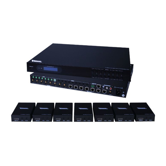
- Page 1 8x7 HDBaseT™ Matrix Selector Switch with Additional HDMI® Output Vanco Part Number: HDBT8x7 Technical Support www.vanco1.com • techsupport@vanco1.com • 800-626-6445...
-
Page 2: Dear Customer
DEAR CUSTOMER Thank you for purchasing this product. For optimum performance and safety, please read these instructions carefully before connecting, operating or adjusting this product. Please keep this manual for future reference. This product is 100% inspected and tested in the United States to verify HDMI performance parameters. - Page 3 Cat5e/6 cable up to 230ft/70m, or 4K signals up to 131ft/40m. The HDBT8X7 is a quick install kit, which includes (7 qty) HDBaseT receivers in the box! Also features Power over Cable (PoC) Technology, which transmits power over Cat5e/6, allowing for the Receiver units to be powered without the use of a power supply.
-
Page 4: Specifications
SPECIFICATIONS Input ................ 8 HDMI HDMI Standard ............Supports HDMI1.4 & HDCP2.2 and is backward compatible with all previous standards Output ..............1 HDMI; 7 HDBaseT Input and Output Level ..........T.M.D.S. 2.9V~3.3V Input and Output Impedance........100Ω (Differential) HDMI Standard ............Supports HDMI1.4 & HDCP1.4 and is backward compatible with all previous standards Video Signal .............. -
Page 5: Panel Descriptions
PANEL DESCRIPTIONS Selector Switch 1. Firmware: Micro USB port for updating firmware 2. Power Indicator: OFF: No power; GREEN: DC power present; RED: Standby Mode 3. 8 input selector buttons & 8 green indicators. num-bered from “1” to “8”. 4. 8 output selector buttons & 8 green indicators, press the buttons to switch input cycle for the outputs 5. -
Page 6: Package Contents
- LINK: HDBT Link status indicator; OFF: No Link; YELLOW:Link Successful; Blinking YELLOW: Link Error. PACKAGE CONTENTS Please check the packaging and make sure the following items are contained in the shipping carton: • HDBT8X7 HDBaseT Matrix Switcher • Optical adapter (for SPDIF audio output) • (7) HDBaseT Receivers •... -
Page 7: Connect And Operate
CONNECT AND OPERATE Source Source Source IR RX HDMI HDMI IR TX IR TX IR TX Cat5e/6 Cat5e/6 Cat5e/6 4K HDBaseT 4K HDBaseT Receiver Receiver HDMI HDMI HDMI HDTV HDTV 1. Connect HDMI sources (e.g. DVD, STB) to HDMI input ports of the Matrix Switcher using good quality HDMI cables. - Page 8 IR CONTROL Connect an IR receiver to the IR EYE port of the Matrix Switcher, users can control it through the included IR remote. Here is a brief introduction to the IR remote. 1. Standby button, press it to enter/ exit standby mode. 2.
- Page 9 IR Emitter (TX) Used to emit IR signal to component that is being controlled. There are mulitple IR functions the HDBT8X7 can handle, and can send IR bi-directionally, however not simultaneously: Control the source(s) from display locations Control the display(s) from the Matrix unit Controlling the SOURCE(S) from the display locations Connect the IR receiver (RX) into the “IR IN”...
- Page 10 Stop bit: 1 Parity bit: non All and any RS-232 documents will be uploaded within the product page of the HDBT8X7 on www.vanco1.com. IP CONTROL The Matrix unit can be controlled via IP. Connect an Ethernet and/or network source such as a network switch or router to the “TCP/IP”...
- Page 11 The Matrix unit can be adjusted for DHCP, see “Network Tab” section. The settings above can be manually adjusted in case the IP address format, Subnet Mask and Gateway are different from the network being utilized at the site. Once the IP settings are saved, test by accessing the Matrix via IP by entering in the IP address into a mobile or web browser that is on the same network, this will give you access to the UI (User Interface) of the Matrix unit.
-
Page 12: Users Tab
Switching the Matrix unit via IP Control The “Main” tab is where to route any input to any output. This is setup like a matrix, simply select the button that matches up the desired Input and Output. The keypad on the right hand side are presets, setting the presets will be covered in the “Configuration”... -
Page 13: Interface Tab
Interface Tab This section allows for renaming of the Matrix unit, as well as renaming the Inputs and Outputs to make it much easier for switching. Instead of “Input 1”, we can now call this “Cable Box” for instance. Remember to hit “Save” to save any changes. Configuration Tab The HDCP compliance tab shows the current HDCP status for each input. -
Page 14: Network Tab
Any available firmware updates will be available within the product page of the HDBT8X7 on www.vanco1.com. The HDBT8X7 can be firmware updated via IP or USB located on the front panel. Documentation and instructions on how to conduct firmware updates will be available with the firmware itself. -
Page 15: Edid Management
EDID MANAGEMENT The HDBT8X7 features EDID management that enables the Matrix Switcher to learn the EDID of all sink (display) devices. The Matrix Switcher can learn the EDID from any device or be programmed to assign an EDID to the mirror port through EDID Invoking. -
Page 16: Troubleshooting
TROUBLE-SHOOTING Problems Causes Solutions Color loss or no video signal The connecting cables may Check whether the cables are output in HDMI display not be connected correctly or connected correctly and in working it may be broken. condition. Fail or loos connection Make sure the connection is good. - Page 17 SAFETY AND NOTICE HDBT8X7 has been tested for conformance to safety regulations and requirements, and has been certified for international use. However, like all electronic equipments, the HDBT8X7 should be used with care. Please read and follow the safety instructions to protect yourself from possible injury and to minimize the risk of damage to the unit.
-
Page 18: Limited Warranty
If repairs are needed during the warranty period the purchaser will be required to provide a sales receipt/sales invoice or other acceptable proof of purchase to the seller of this equipment. The seller will then contact Vanco regarding warranty repair or replacement. -
Page 19: Technical Support
TECHNICAL SUPPORT In case of problems, please contact Vanco Technical Support by dialing 1-800-626-6445. You can also email technical support issues to techsupport@vanco1.com. When calling, please have the Model Number, Serial Number (affixed to the bottom of the unit) and Invoice available for reference during the call. - Page 20 Vanco® International 506 Kingsland Drive Batavia, Illinois 60510 call: 800.626.6445 fax: 630.879.9189 visit: www.vanco1.com...
Need help?
Do you have a question about the HDBT8x7 and is the answer not in the manual?
Questions and answers